Setup Overview
for the HPE ProLiant DL180 Gen9 Server
Before you begin
- For safety, environmental, and regulatory information, see Safety and Compliance Information for Server, Storage, Power, Networking, and Rack Products on the Hewlett Packard Enterprise website.
- Select an installation site that meets the detailed installation site requirements described in the server user guide.
- Unpack the server shipping carton, and locate the materials and documentation necessary for installing the server.
Verify operating system support—For information about operating systems supported by ProLiant servers, see the operating system support matrices.
For more pre-installation information, see the HPE ProLiant DL180 Gen9 Server User Guide.
Component identification
Front panel components
- 4-bay LFF non-hot-plug drive model

Item
Description
1
LFF non-hot-plug drives
2
USB 2.0 connector
- 8-bay LFF hot-plug drive model
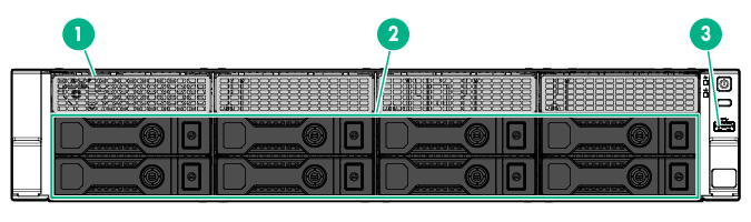
Item
Description
1
Box 1 LFF hot-plug drives
2
Box 2 LFF hot-plug drives
3
USB 3.0 connector
- 8-bay SFF hot-plug drive model
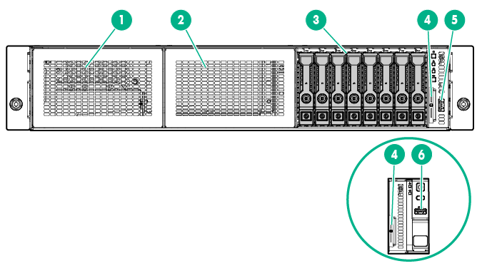
Item
Description
1
Universal Media Bay (box 1, for the optical drive cage option)
2
8-bay SFF drive cage bay (box 2, for the second 8-bay SFF drive cage option)
3
Box 3 SFF hot-plug drives
4
Serial label pull tab
5
USB 2.0 connector (in servers using thumbscrew rack ears)
6
USB 3.0 connector (in servers using quick-release latch rack ears)
Serial label pull tab
The vertically oriented serial label pull tab in the SFF chassis is double-sided. The following server labels are attached to this pull tab:
- Left side—Server serial number label and the customer asset tag label
- Right side—Default iLO account information label and the QR code label
Use your mobile device to scan the QR code label to display the server mobile product page. This page contains links to server setup information, spare part numbers, QuickSpecs, troubleshooting resources, and other useful product links.
In the LFF chassis, these server labels are attached on the front edge of the access panel instead.
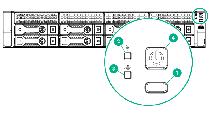
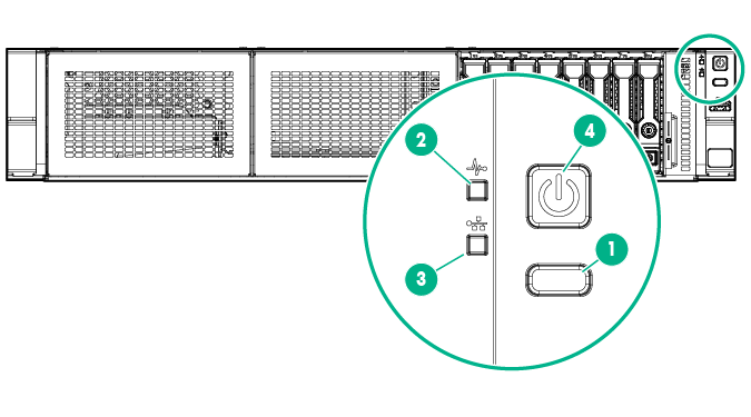
Front panel LEDs and buttons
- Front panel LEDs and buttons in an LFF chassis with thumbscrew rack ears
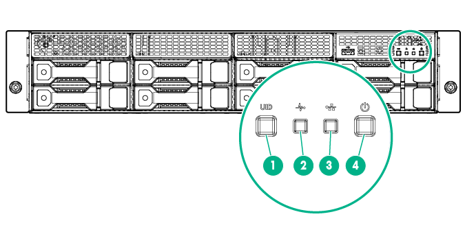
- Front panel LEDs and buttons in an LFF chassis with quick-release latch rack ears
- Front panel LEDs and buttons in an SFF chassis with thumbscrew rack ears
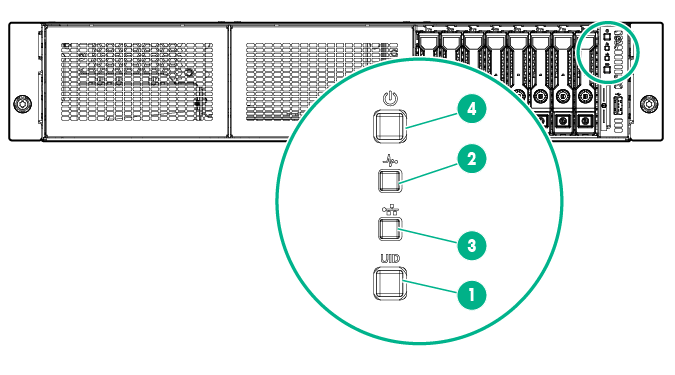
- Front panel LEDs and buttons in an SFF chassis with quick-release latch rack ears
Item
Description
Status
1
UID button/LED
Solid blue = Activated
Flashing blue:
- 1 flash per second = Remote management or firmware upgrade in progress
- 4 flashes per second = iLO manual reboot sequence initiated
- 8 flashes per second = iLO manual reboot sequence in progress
Off = Deactivated
2
Health LED
Solid green = Normal
Flashing green (1 flash per second) = iLO is rebooting
Flashing amber = System degraded
Flashing red (1 flash per second) = System critical
If the health LED indicates a degraded or critical state, review the system IML or use iLO to review the system health status.
3
NIC status LED
Solid green = Link to network
Flashing green (1 flash per second) = Network active
Off = No network activity
4
Power On/Standby button and system power LED
Solid green = System on
Flashing green (1 flash per second) = Performing power on sequence
Solid amber = System in standby
Off = No power present
If the system power LED is off, verify the following conditions:
- The facility power is present.
- The power supply is installed and is working correctly.
- The power cord is attached and is connected to a power source.
- The front I/O cable is connected.
When all four LEDs described in this table flash simultaneously, a power fault has occurred. For more information, see "Front panel LED power fault codes" in the HPE ProLiant DL180 Gen9 Server User Guide.
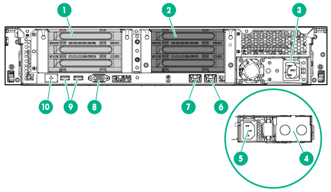
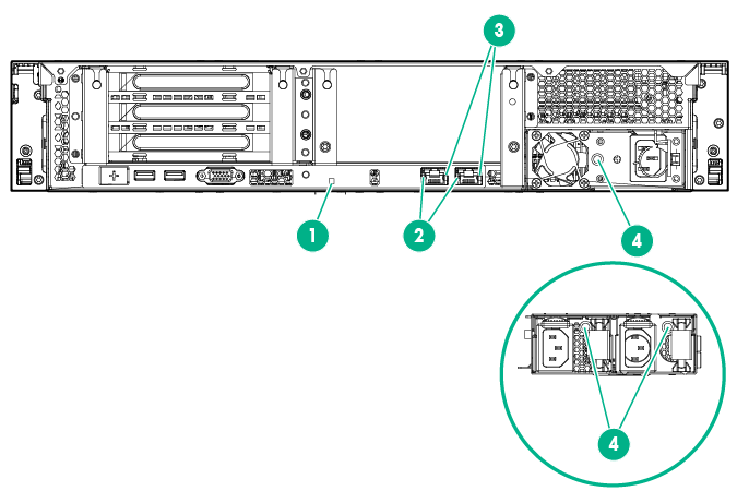
Rear panel components
Item |
Description |
|---|---|
1 |
PCIe3 riser slots 1-3 (primary, associated with processor 1) |
2 |
PCIe3 riser slots 4-6 (secondary, associated with processor 2) |
3 |
Non-hot plug power supply |
4 |
Hot-plug power supply bay 2 |
5 |
Hot-plug power supply 1 |
6 |
NIC connector 2 |
7 |
NIC 1/shared iLO connector |
8 |
Video connector |
9 |
USB 3.0 connectors |
10 |
Dedicated iLO management connector (optional) |
Rear panel LEDs
Item |
Description |
Status |
|---|---|---|
1 |
UID LED |
Solid blue = Activated Flashing blue:
|
2 |
NIC link LED |
Green = Network link Off = No network link |
3 |
NIC activity LED |
Solid green = Link to network Flashing green = Network active Off = No network activity |
4 |
Power supply LED |
Solid green = Normal Off = One or more of the following conditions exists:
|
Install hardware options
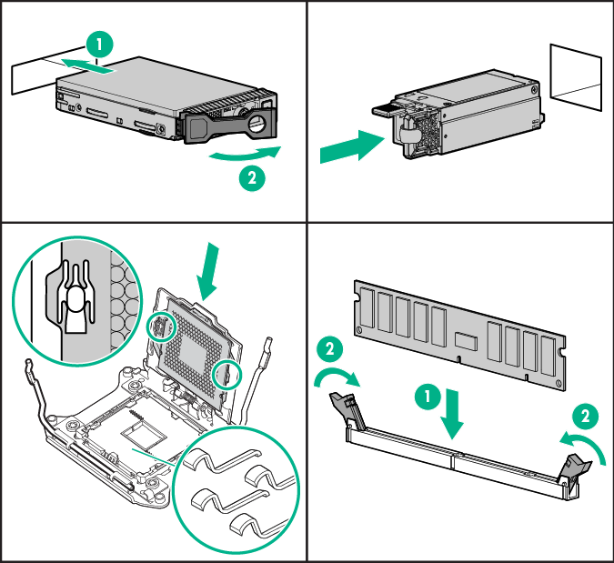
Install any hardware options before initializing the server. For options installation information, see the documentation that ships with the option. For server specific information, see the HPE ProLiant DL180 Gen9 User Guide.
Install the server in the rack
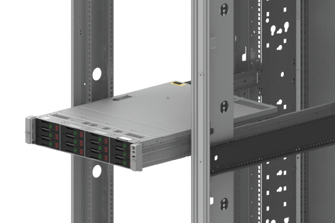
Install the server and cable management into the rack. Before you begin installation, be sure to review the warnings and cautions, as well as the installation instructions that ships with the 2U Easy Install Rail Kit.
Before installing the server, be sure that you understand the following warnings and cautions.
|
WARNING: To reduce the risk of personal injury or damage to the equipment, be sure that:
|
|
WARNING: To reduce the risk of personal injury or equipment damage when unloading a rack:
|
|
WARNING: To reduce the risk of personal injury or damage to the equipment, adequately stabilize the rack before extending a component outside the rack. Extend only one component at a time. A rack may become unstable if more than one component is extended. |
|
WARNING: When installing a server in a telco rack, be sure that the rack frame is adequately secured at the top and bottom to the building structure. |
|
WARNING: This server is very heavy. To reduce the risk of personal injury or damage to the equipment:
|
|
CAUTION: Protect the server from power fluctuations and temporary interruptions with a regulating uninterruptible power supply. This device protects the hardware from damage caused by power surges and voltage spikes and keeps the system in operation during a power failure. |
|
CAUTION: Do not operate the server for long periods with the access panel open or removed. Operating the server in this manner results in improper airflow and improper cooling that can lead to thermal damage. |
Connect cabling and power cords
- Connect the iLO management cabling.
The dedicated iLO connector shown in the image is an optional component. If you do not have this option installed, the iLO management connection will be routed through the NIC 1/shared iLO connector.
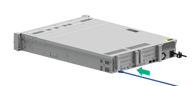
- Connect the network cabling.
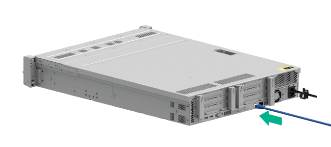
- Connect the power cord to the power supply.


WARNING: To reduce the risk of electric shock or damage to the equipment:
- Do not disable the power cord grounding plug. The grounding plug is an important safety feature.
- Plug the power cord into a grounded (earthed) electrical outlet that is easily accessible at all times.
- Unplug the power cord from the power supply to disconnect power to the equipment.
- Do not route the power cord where it can be walked on or pinched by items placed against it. Pay particular attention to the plug, electrical outlet, and the point where the cord extends from the server.
For more information about cabling the system, see the HPE ProLiant DL180 Gen9 User Guide.
Power up and select boot options
On servers operating in UEFI Boot Mode, the boot controller and boot order are set automatically.
- Press the Power On/Standby button.
- During the initial boot:
- To modify the server configuration ROM default settings, press the F9 key in the ProLiant POST screen to enter the UEFI System Utilities screen. By default, the System Utilities menus are in the English language.
- If you do not need to modify the server configuration and are ready to install the system software, press the F10 key to access Intelligent Provisioning.
For more information on automatic configuration, see the UEFI documentation on the Hewlett Packard Enterprise website.
Install the system software
This ProLiant server does not ship with provisioning media. Everything needed to manage and install the system software and firmware is preloaded on the server.
To operate properly, the server must have a supported operating system. Attempting to run an unsupported operating system can cause serious and unpredictable results. For the latest information on operating system support, see the Hewlett Packard Enterprise website.
Failure to observe UEFI requirements for ProLiant Gen9 servers can result in errors installing the operating system, failure to recognize boot media, and other boot failures. For more information on these requirements, see the HPE UEFI Requirements on the Hewlett Packard Enterprise website.
To install an operating system on the server, use one of the following methods:
- Intelligent Provisioning—For single-server deployment, updating, and provisioning capabilities.
To install an operating system on the server with Intelligent Provisioning (local or remote):
- Connect the Ethernet cable between the network connector on the server and a network jack.
- Press the Power On/Standby button.
- During server POST, press F10.
- Complete the initial Preferences and Registration portion of Intelligent Provisioning.
- At the 1 Start screen, click Configure and Install.
- To finish the installation, follow the onscreen prompts. An Internet connection is required to update the firmware and systems software.
- Insight Control server provisioning—For multi-server remote OS deployment, use Insight Control server provisioning for an automated solution. For more information, see the Insight Control documentation on the Hewlett Packard Enterprise website.
For additional system software and firmware updates, download the Service Pack for ProLiant from the Hewlett Packard Enterprise website. Software and firmware must be updated before using the server for the first time, unless any installed software or components require an older version.
For more information, see the "Keeping the system current" section in the HPE ProLiant DL180 Gen9 User Guide.
For more information on using these installation methods, see the Hewlett Packard Enterprise website.
Register the server
To experience quicker service and more efficient support, register the product at the Hewlett Packard Enterprise Product Registration website.
Additional information
For more information, see the HPE ProLiant DL180 Gen9 Server documentation in the Hewlett Packard Enterprise Information Library.
For important safety, environmental, and regulatory information, see Safety and Compliance Information for Server, Storage, Power, Networking, and Rack Products, available at the Hewlett Packard Enterprise website.
Hewlett Packard Enterprise is committed to providing documentation that meets your needs. To help us improve the documentation, send any errors, suggestions, or comments to Documentation Feedback. When submitting your feedback, include the document title, part number, edition, and publication date located on the front cover of the document. For online help content, include the product name, product version, help edition, and publication date located on the legal notices page.
Part number: 790464-005
August 2018
Edition: 5