| |
| |
The 5400R zl2 switches are designed to be mounted in any EIA-standard 19-inch telco rack or in an equipment cabinet such as a server cabinet. If you are installing the switch in an equipment cabinet, read the following note:
NOTE: If you are installing the switch in an equipment cabinet, in place of the 12-24 screws supplied with the switch, use the clips and screws that came with the cabinet. Plan which four holes that you will be using in the cabinet and install all four clips and partially install the two bottom screws, as described in step 2 on the previous page, before proceeding to step 3. The number of holes depends on the switch and the rack kit being used. To reduce the switch weight and ease while installation, you can remove the power supplies during the racking process. | |
WARNING! For safe operation, please read “1. Review installation precautions” before mounting the switch. | |
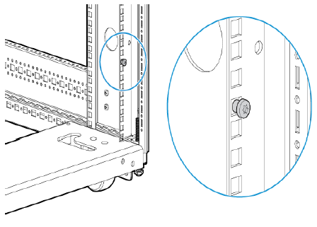
Determine position of switch in rack and install a cage nut in the lower hole of the lowest rack unit.
Install a screw half-way into this cage nut.
Align the included Rack Mount Bracket such that the half-hole lines up with the screw, install additional cage nuts at each hole position in the bracket.
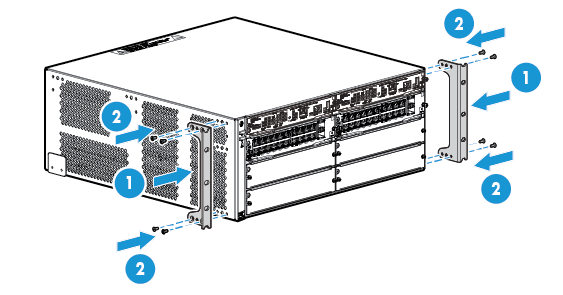
1 | Rack Brackets |
2 | Flat Head screws |
Repeat for opposite column in the rack.
Secure the Rack Mount Brackets to the switch with included flat head screws.
NOTE: Use only the included 6 mm/0.24 inch flat head screws. Using any of the 8 mm/0.31 inch screw included in other rack mounting kits interferes with internal components. | |
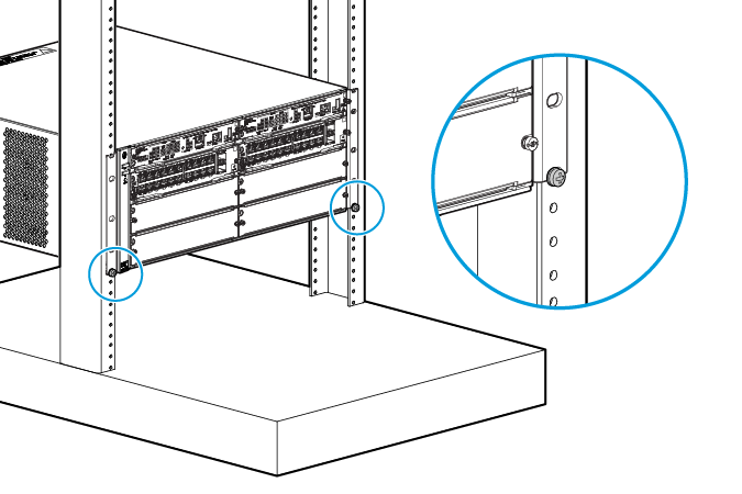
Rest the switch on the two half-way installed screws and secure the switch to the rack using the top hole in each Rack Mount Bracket.
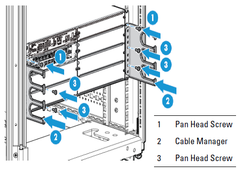
Align each Cable Manager such that two holes in the Cable Manager align with two empty holes in the Rack Mount Bracket and secure with two screws.
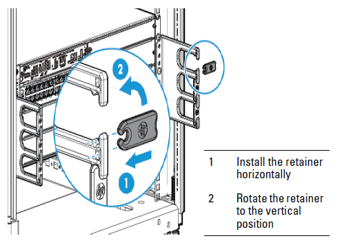
Snap the Cable Retainers into the arms of the Cable Managers.