|
|
|


Installing the processor
The processors and memory are located in the drawer accessible from the front of the server. It is not necessary to extend or remove the server from the rack to install or replace processors and memory.
|
WARNING: Use caution when installing or removing the processor memory drawer. The processor memory drawer is very heavy when fully populated. |
|
CAUTION: To prevent possible server malfunction and damage to the equipment, multiprocessor configurations must contain processors with the same part number. |
|
IMPORTANT: If installing a processor with a faster speed, update the system ROM before installing the processor. |
|
IMPORTANT: Update the system BIOS prior to installing processor generation upgrades. |
To install the component:
- Update the system ROM.
Locate and download the latest ROM version from the HP website. Follow the instructions on the website to update the system ROM.
- Power down the server.
- Remove all power:
- Disconnect each power cord from the power source.
- Disconnect each power cord from the server.
- Remove the processor memory drawer shipping screws, if installed. Retain the screws for future use.
- Remove the processor memory drawer.
- Remove the processor memory drawer cover.

CAUTION: The pins on the processor socket are very fragile. Any damage to them may require replacing the system board.
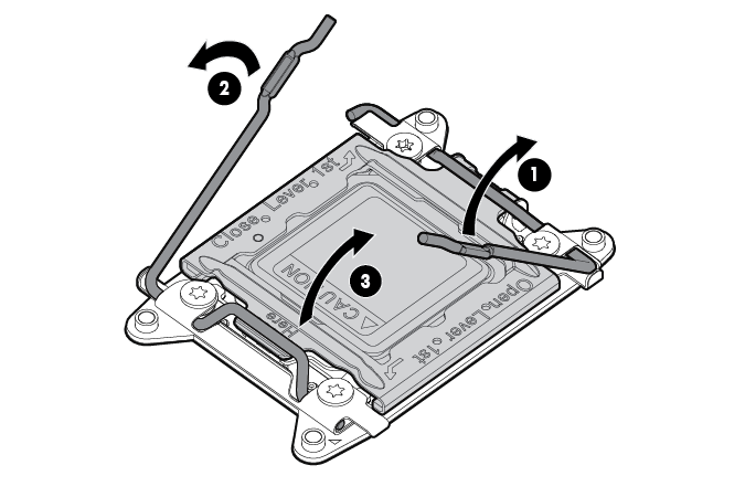
- Open each of the processor locking levers in the order indicated, and then open the processor retaining bracket.
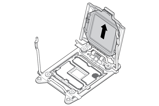
- Remove the clear processor socket cover. Retain the processor socket cover for future use.
- Install the processor. Verify that the processor is fully seated in the processor retaining bracket by visually inspecting the processor installation guides on either side of the processor. THE PINS ON THE SYSTEM BOARD ARE VERY FRAGILE AND EASILY DAMAGED.
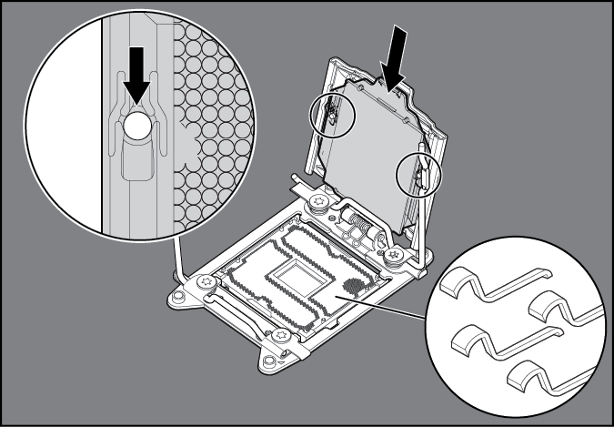
CAUTION: THE PINS ON THE SYSTEM BOARD ARE VERY FRAGILE AND EASILY DAMAGED. To avoid damage to the system board, do not touch the processor or the processor socket contacts.
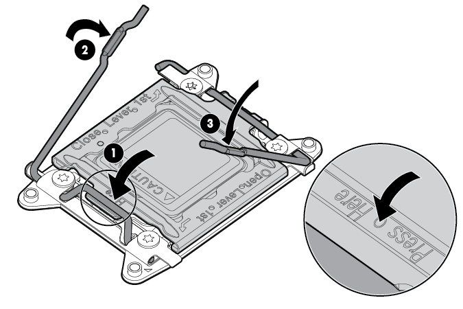
- Close the processor retaining bracket. When the processor is installed properly inside the processor retaining bracket, the processor retaining bracket clears the flange on the front of the socket.
CAUTION: Do not press down on the processor. Pressing down on the processor may cause damage to the processor socket and the system board. Press only in the area indicated on the processor retaining bracket.
- Press and hold the processor retaining bracket in place, and then close each processor locking lever. Press only in the area indicated on the processor retaining bracket.
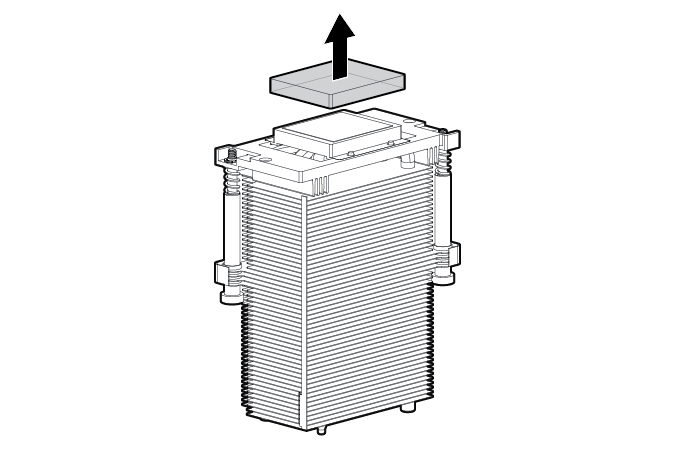
- Remove the thermal interface protective cover from the heatsink.
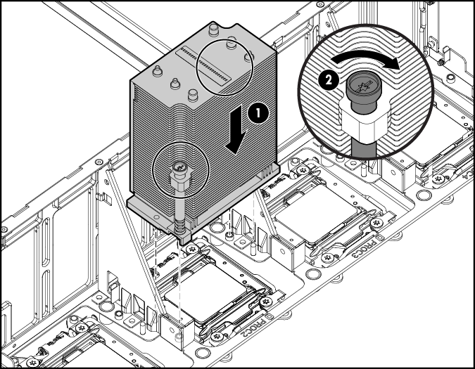
CAUTION: To prevent the heatsink from tilting to one side during installation and removal procedures, use a diagonally opposite pattern (an “X” pattern) when loosening and tightening the two spring-loaded screws. To prevent the screws from breaking off, do not over-tighten the screws. A maximum torque of 0.45 N m (4 in-Ib) is set for the system.
- Install the heatsink.
- Install the processor memory drawer cover.
- Install the processor memory drawer.
- Connect each power cord to the server.
- Connect each power cord to the power source.
- Power up the server.