Prerequisites
Before you perform this procedure:
Make sure that you have the latest firmware for the controllers and the expander card. To download the latest firmware, see the
Hewlett Packard Enterprise website.
Note the port numbering on the:
Make sure you have the following items available:
Procedure
-
Remove the front bezel.
-
Power down the server.
-
Remove all power:
- Disconnect each power cord from the power source.
- Disconnect each power cord from the
server.
-
Disconnect all peripheral cables from the server.
-
Do one of the following:
-
Remove the access panel.
-
Remove the air baffle.
-
If installed,
remove the fan cage.
-
Remove the PCI blank retainer.
-
Remove the blanks opposite the processor 1 PCIe3 expansion slots where the expander card and the standup storage controller board will be installed.
In this server, the expander card is supported in the PCIe3 expansion slots 2 and 4.
-
Remove the PCI board screws opposite the selected slots.
-
Observe the guidelines for managing cables.
-
Connect the Mini-SAS X-cables to the expander card.
-
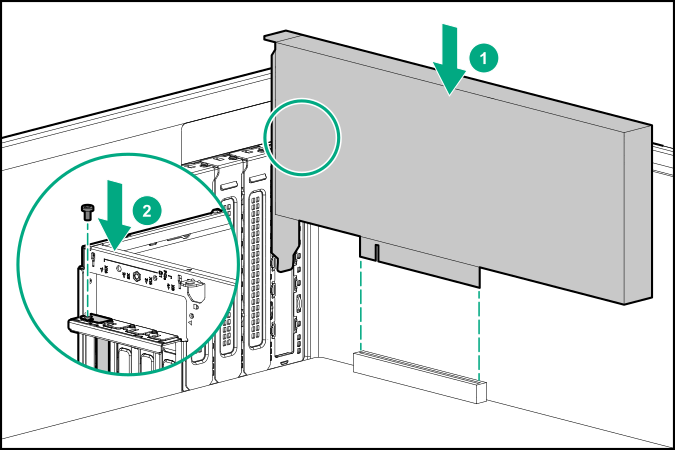
Install the SAS expander card.
-
Make sure that the card is firmly seated in the slot.
-
If you are using the expander card with a standup controller, do the following:
- Install the standup controller.
- Connect the 876502-001 Mini-SAS X-cable to the standup controller.
- Connect the following Mini-SAS X-cables to the drive backplanes:
876482-001 Mini-SAS X-cable = Drive box backplane 1
876483-001 Mini-SAS X-cable = Drive box backplane 2
876484-001 Mini-SAS X-cable = Drive box backplane 3
-
If you are using the expander card with a modular controller (AROC), do the following:
- Install the modular controller.
- Route and connect the 876495-001 Mini-SAS X-cable to the modular controller.
- Route and connect the following Mini-SAS X-cables to the drive backplanes:
876482-001 Mini-SAS X-cable = Drive box backplane 1
876483-001 Mini-SAS X-cable = Drive box backplane 2
876484-001 Mini-SAS X-cable = Drive box backplane 3
-
Install the PCI blank retainer.
-
If the fan cage was removed, do the following:
- Make sure that all the system cables that are routed through the front cable channel are properly secured in the metal cable tabs. This is done to prevent system damage due to cables being inadvertently caught under the fan cage.
- Install the fan cage.
-
Install the air baffle.
-
Install the access panel.
-
Do one of the following:
-
Connect all peripheral cables to the server.
-
Connect each power cord to the server.
-
Connect each power cord to the power source.
-
Power up the server.
-
Install the front bezel.
-
Configure the storage controller.
The installation is complete.