Disconnect all cables connected to the system board.
Remove the system board:
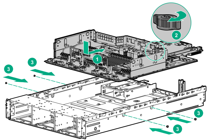
Remove the screws from the side of the
server.
Loosen the thumbscrew.
Slide the system board toward the front of the
server, and then lift it from the
server.
Replacing the system board
Install the spare system board.
IMPORTANT: Install all components with the same configuration that was used on the failed system board.
Install all components removed from the failed system board.
Be sure to install the DIMMs and
HPE Persistent Memory modules in the same DIMM slots as the failed system board.
Install the fan cage.
If removed, do the following:
Install the air baffle.
Install the processor mezzanine tray.
Install the CPU Mezzanine UPI performance kit.
Install the access panel.
Install the
server into the rack.
Connect the power cord to the power supply.
CAUTION:
Connect the power cords using only the following supported configurations. Using an unsupported power supply or cabling configuration can result in an unexpected loss of system power.
Two power supply configuration—For redundancy, connect power supplies 1 and 2 to separate AC power circuits.
Four power supply configuration—For redundancy, connect power supplies 1 and 2 to power circuit A, and then connect power supplies 3 and 4 to power circuit B.
Power up the
server.
Ensure all firmware, including option cards and embedded devices, is updated to the same versions to ensure that the latest drivers are being used.
Re-enter any Secure Boot Keys that were previously added in the Secure Boot configuration.
If
HPE Persistent Memory modules are encrypted with local key management, either manually enter the
HPE Persistent Memory module passwords in the System Utilities or import the password file from the USB key.
If
HPE Persistent Memory modules are encrypted with remote key management, enroll the
server iLO in the key management server to provide access to the data on the
HPE Persistent Memory modules.