|
|
|


SAS expander card option
- Power down the server.
- Remove all power:
- Disconnect each power cord from the power source.
- Disconnect each power cord from the server.
- Extend the server from the rack.
- Remove the access panel.
- Depending on the server options installed, do one of the following:
- Remove the fan cage.
- Remove the primary PCI riser cage.
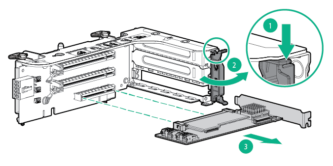
- Disconnect the cables from the expander card.
- Remove the expander card.
To replace the component:
- Remove the primary PCI riser cage.

IMPORTANT: The 12G SAS Expander Card is not supported in the secondary PCI riser cage.
- Install the SAS expander card. The cables are not shown for clarity.
IMPORTANT: The 12G SAS Expander Card is only supported in slot 2.
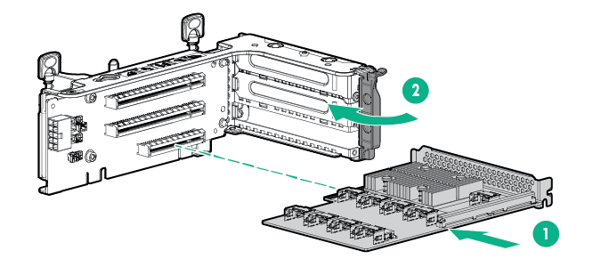
IMPORTANT: If using a PCI slot-based controller, install the controller in slot 1.
- Install the PCI riser cage.
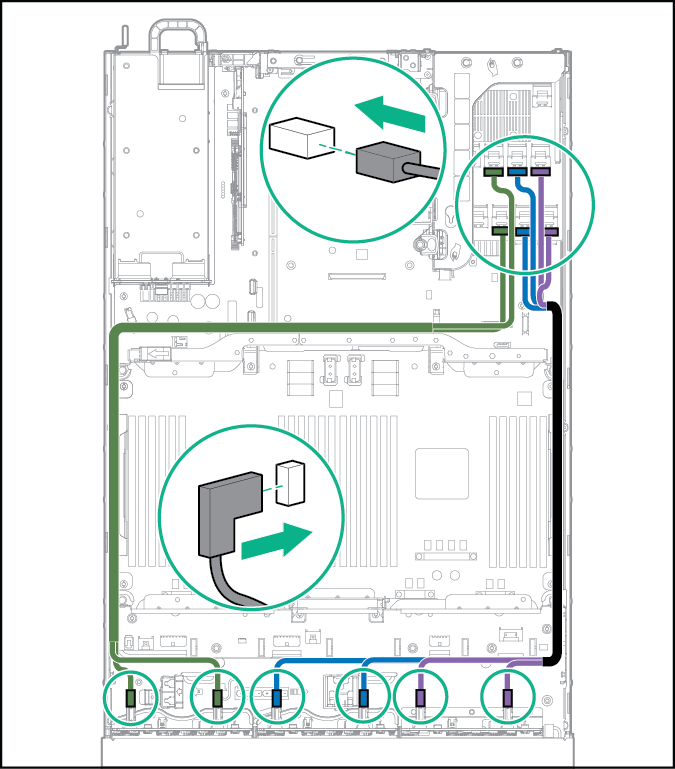
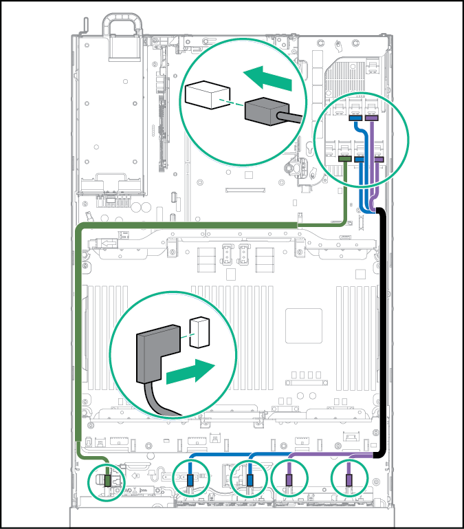
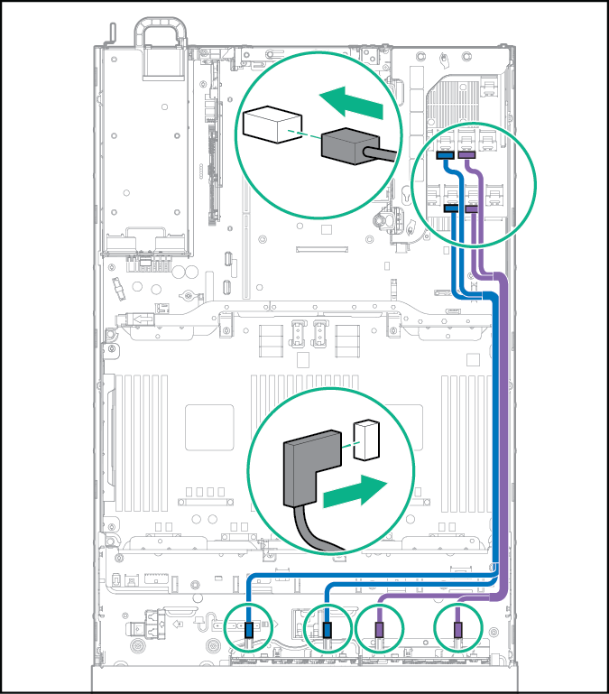
- Using the labels on the cables to determine the correct connections, connect the cables from the SAS expander card to the controller:
- HPE Flexible Smart Array Controller with 2 x4 connectors (Group B SAS cables)
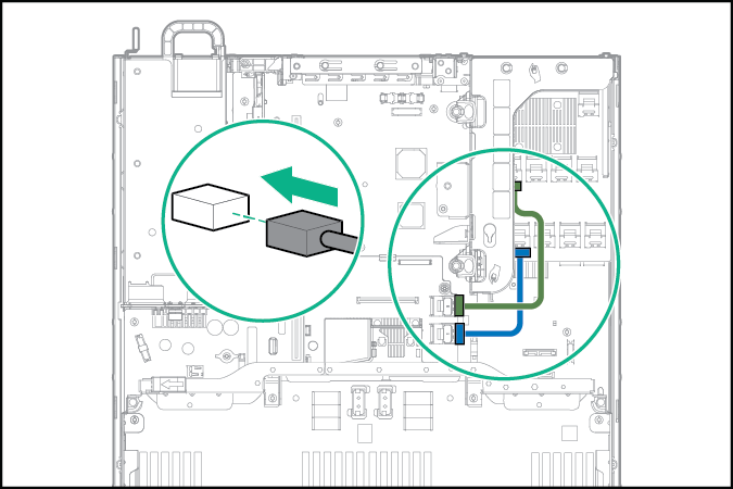
- PCI slot-based Smart Array controller with x8 connector (Group A SAS cables)
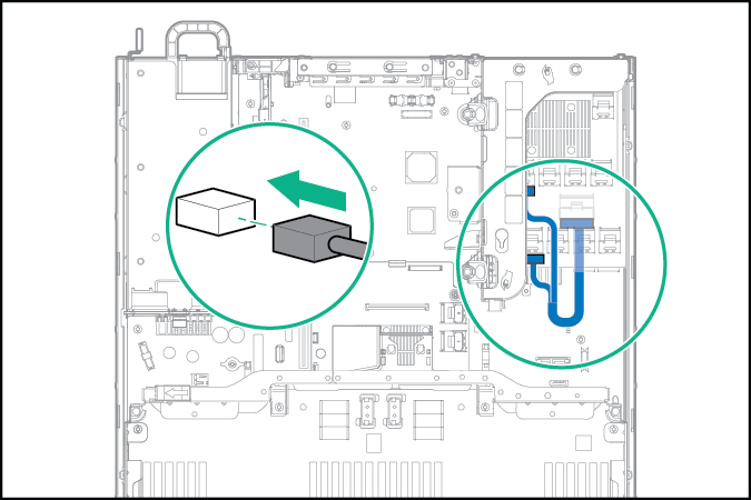
- HPE Flexible Smart Array Controller with 2 x4 connectors (Group B SAS cables)
- Connect the cables to the drive cage backplanes:
IMPORTANT: You might need to remove the far right DIMM to route cables through the cable trough. After the cables have been routed, install the DIMM.
- 24SFF backplanes (Group C SAS cables)
- 18SFF backplanes (Group C SAS cables)
- 16SFF backplanes (Group C SAS cables)
- 24SFF backplanes (Group C SAS cables)
- Install the fan cage.
- Depending on the server options installed, do one of the following:
- Install the access panel.
- Install the server into the rack.
- Connect each power cord to the server.
- Connect each power cord to the power source.
- Power up the server.
To replace the component, reverse the removal procedure.