|
|
|


Redundant power supply option
Install the RPS enablement option to improve power efficiency and enable power redundancy. Power efficiency requires the installation of one power input module and power redundancy requires the installation of two power input modules. This module is a separately purchased option and is not part of the RPS enablement option kit.
When this RPS backplane enablement option and a single power input module are installed in the server, you can install or remove a second power input module without powering down the server.
|
WARNING: To reduce the risk of electric shock or damage to the equipment:
|
|
WARNING: To reduce the risk of injury from electric shock hazards, do not open power supplies. Refer all maintenance, upgrades, and servicing to qualified personnel. |
|
WARNING: To reduce the risk of personal injury from hot surfaces, allow the drives and the internal system components to cool before touching them. |
|
CAUTION: To prevent damage to electrical components, properly ground the server before beginning any installation procedure. Improper grounding can cause ESD. |
|
CAUTION: To prevent improper cooling and thermal damage, do not operate the server unless all bays are populated with either a component or a blank. |
For more information about product features, specifications, options, configurations, and compatibility, see the product QuickSpecs on the Hewlett Packard Enterprise website.
To install the component:
- Power down the server.
- Remove all power:
- Disconnect each power cord from the power source.
- Disconnect each power cord from the server.
- Place the server on a sturdy, level surface.
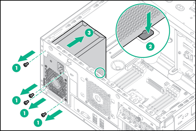
- Remove the access panel.
- If installed, remove the PCI air baffle.
- Remove the system air baffle.
- Disconnect all power supply cables from the system board, drive cages, and devices.
- Remove the existing power supply.
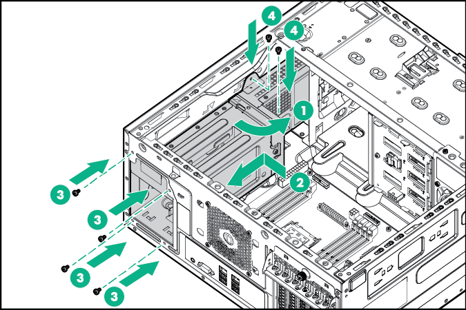
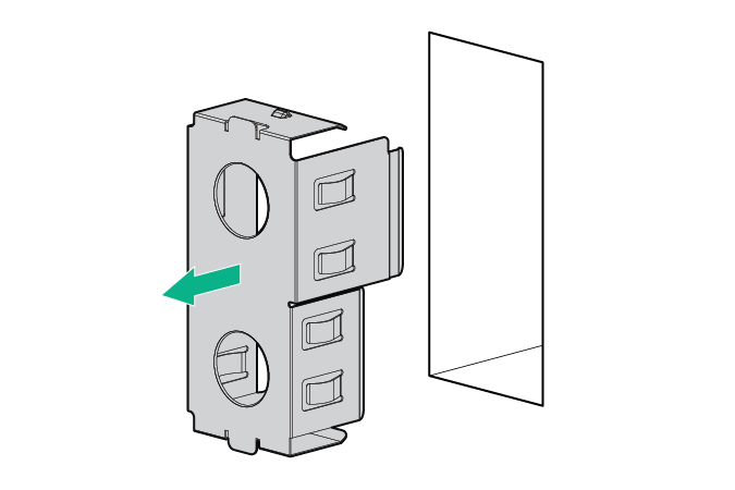
- Insert and install the RPS bracket into the bay.
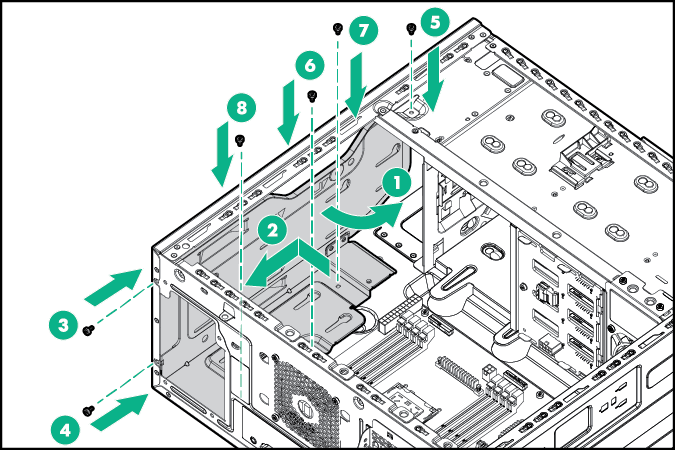

CAUTION: To prevent damage to other components in the server, insert the RPS enablement option into the bay carefully.
- Grab the power supply cables from the RPS backplane assembly and then insert the backplane into the bay carefully.
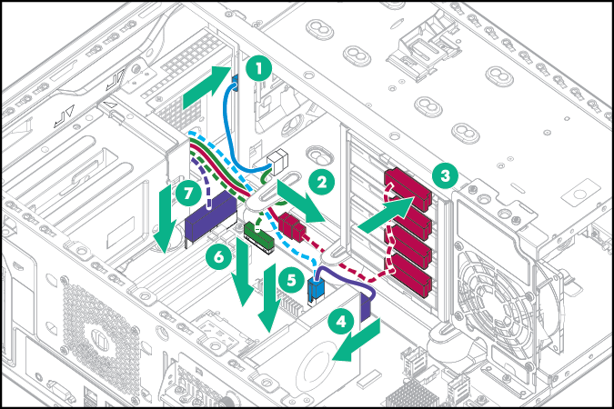
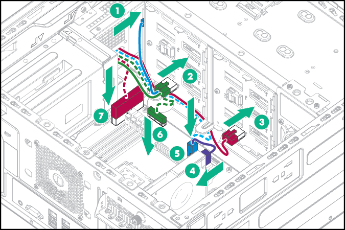
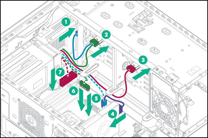
- Connect the RPS backplane cables and then route the cables underneath the metal tabs:
- 4 LFF non-hot-plug configuration
- Optical drive power cable to optical drive
- 8-pin drive power cable to the non-hot-plug drive power connector
- 4-pin power cable to system board
- 6-pin power cable to GPU, if installed
- RPSU cable to system board
- 24-pin power cable to system board
- 4 LFF and 8 SFF hot-plug configuration
- Optical drive power cable to optical drive
- 8-pin drive power cable to the hot-plug drive backplanes
- 4-pin power cable to system board
- 6-pin power cable to GPU, if installed
- RPSU cable to system board
- 24-pin power cable to system board
4 LFF hot-plug configuration
8 SFF hot-plug configuration
- 4 LFF non-hot-plug configuration
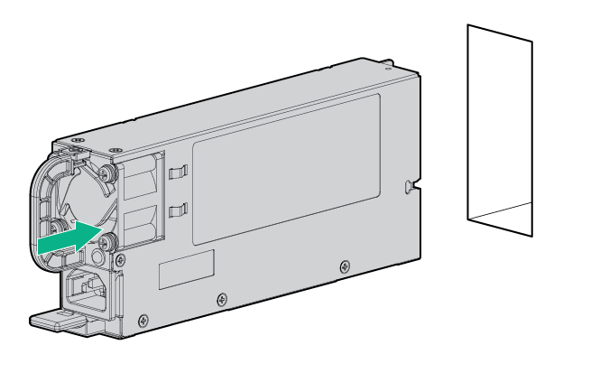
- Install a hot-plug power input module in the power supply bay 1.
NOTE: When facing the rear of the server in an upright position, the upper level of power supply bay is bay 1 and the lower level is bay 2.
- If you intend to enable power redundancy in the server, install a second power input module in the power supply bay 2:
- Remove the power supply blank from bay 2.
- Install a second hot-plug power input module in the power supply bay 2.
CAUTION: To prevent improper cooling and thermal damage, do not operate the server unless all bays are populated with either a component or a blank.
- Remove the power supply blank from bay 2.
- Install the system air baffle.
- If removed, install the PCI air baffle.
- Install the access panel.
- Connect the power cords to the power supplies.
- Connect the power cords to the AC power source.
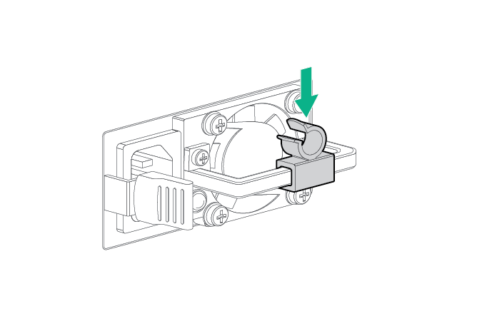
- Install the strain relief clip.
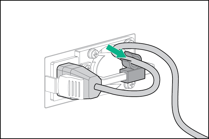
- Route and manage the power cords through strain relief clip.
- Power up the server.