|
|
|


Express Bay enablement option
|
CAUTION: To prevent damage to electrical components, take the appropriate anti-static precautions before beginning any system installation. Improper grounding can cause electrostatic discharge. |
- Power down the server.
- Remove all power:
- Disconnect each power cord from the power source.
- Disconnect each power cord from the server.
- Remove the server from the rack.
- Remove the access panel.
- Install the backplane, and then tighten the thumbscrews.
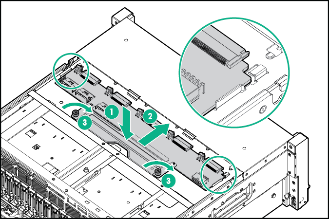
Be sure the corners of the backplane are aligned under the tabs.

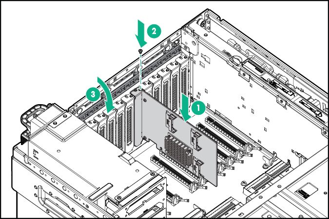
IMPORTANT: The Express Bay Bridge Card should only be installed in a slot with a x16 electrical connection, and with the required processor installed. For example, slot 1 is a x16 connection but requires processor 4 to also be installed.
- Install the card into an available negotiable link PCI. For slot identification, see "I/O board components."
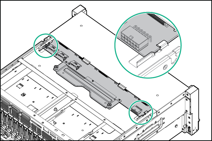
- Connect the power and data cables.
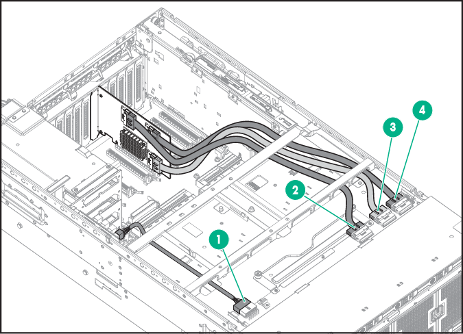
Item
Description
1
Power connection to the system board
2
Data connection to drives 6 and 7
3
Data connection to drives 8 and 9
4
Data connection to drive 10
- Install the access panel.
- Remove all bezel blanks.
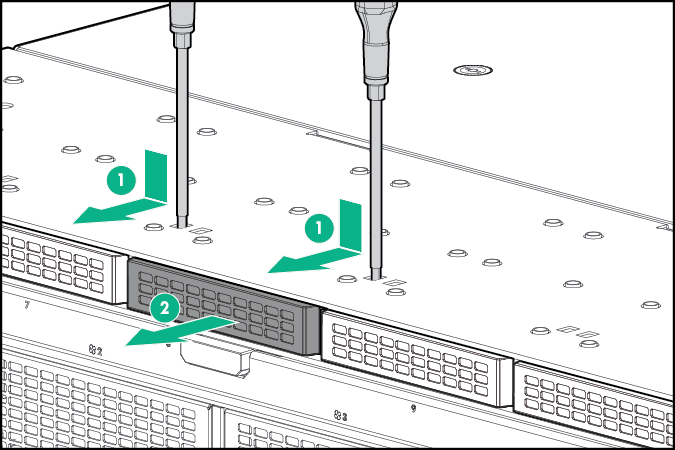
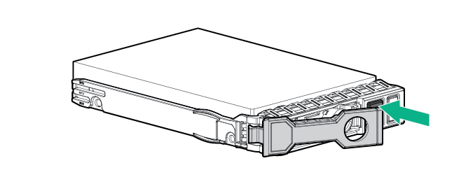
- Press the Do Not Remove button to open the release handle.
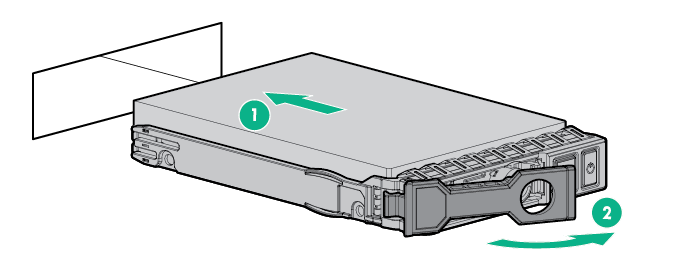
- Install the drives.

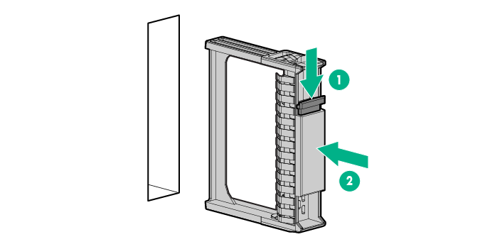
CAUTION: To prevent improper cooling and thermal damage, do not operate the server unless all bays are populated with either a component or a blank.
- Install the drive blank in any unused drive bays.
- Connect each power cord to the server.
- Connect each power cord to the power source.
- Power up the server.