Tower to rack conversion

WARNING: This server is heavy. To reduce the risk of personal injury or damage to the equipment:
  • Observe local occupational health and safety requirements and guidelines for manual material handling.
  • Get help to lift and stabilize the product during installation or removal, especially when the product is not fastened to the rails. Hewlett Packard Enterprise recommends that a minimum of two people are required for all rack server installations. A third person may be required to help align the server if the server is installed higher than chest level.
  • Use caution when installing the server in or removing the server from the rack; it is unstable when not fastened to the rails.
CAUTION: Always plan the rack installation so that the heaviest item is on the bottom of the rack. Install the heaviest item first, and continue to populate the rack from the bottom to the top.

Procedure

  1. Back up all server data, and record configuration information.
  2. Close all applications, and then shut down the operating system.
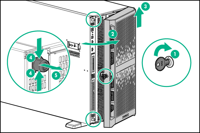
  3. Unlock and remove the tower bezel from the chassis, and then remove the standoffs.
    Removing the front bezel and standoffs
  4. Power off the server by pressing the power button on the front of the server.
  5. Disconnect all AC power cords from the AC outlets, and then disconnect all AC power cords from the server.
  6. Place the server on its side on a flat, level work surface.
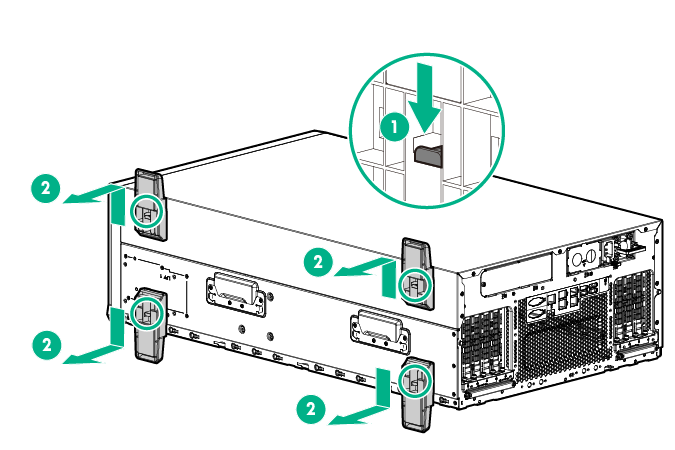
  7. Remove the server base feet.
    Removing the server base feet
  8. Remove all screws securing the base cover to the chassis.
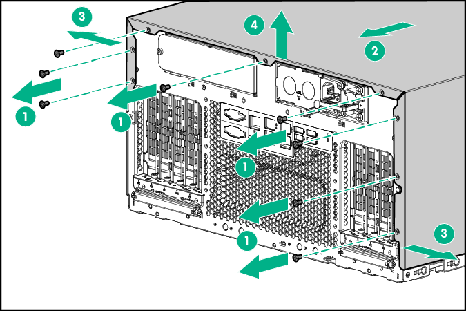
  9. Slide the base cover toward the rear of the server, and then remove the base cover.
    Removing the base cover
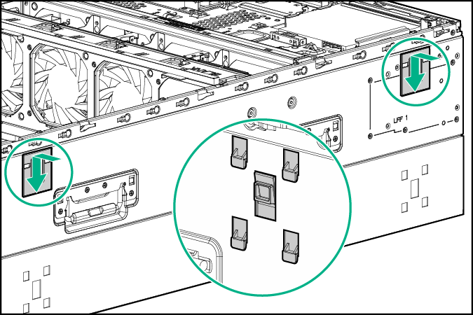
  10. Install the server base blank covers over the server base feet holes.
    Installing the server base blank covers
  11. Turn the server over, and then remove the access panel.
  12. Remove the air baffle.
  13. Remove the fan cage.
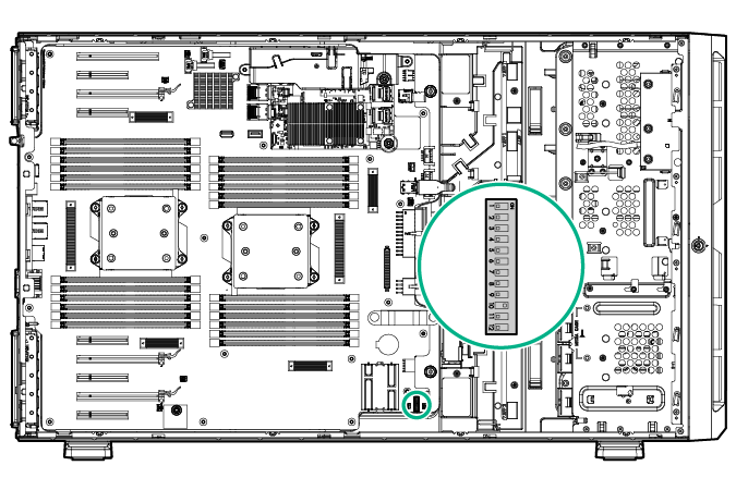
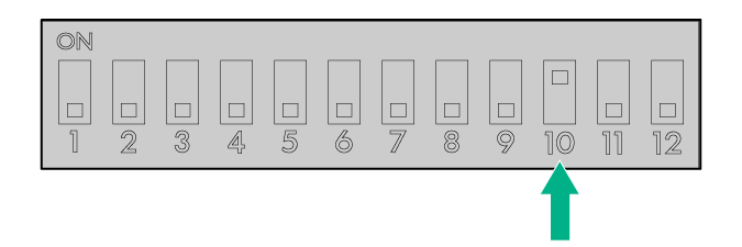
  14. Locate the system maintenance switch on the system board.
    Locating the system maintenance switch on the system board
  15. Configure position 10 of the system maintenance switch to ON for a rack configuration.
    Configuring the system maintenance switch for rack mounting
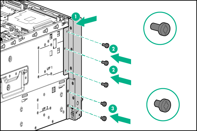
  16. Install the left and right rack bezel ears.
    1. Insert and completely tighten the 3 long silver T-15 screws on the upper side of each rack bezel ear.
    2. Insert and completely tighten the 2 short black T-15 screws on the lower side of each rack bezel ear.
      Installing the left ear bezel
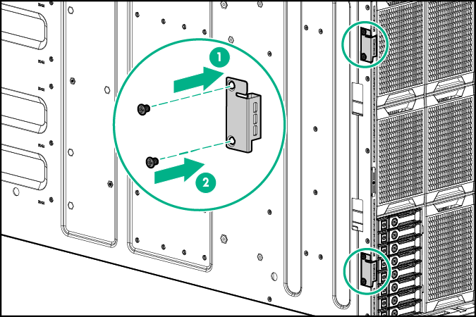
  17. Install the front bezel hinge covers.
    Installing the front bezel hinge cover
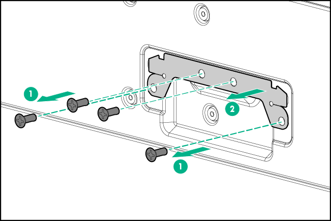
  18. Remove the handle hole covers from the chassis, and retain the screws.
    Removing mylar sheets from the chassis
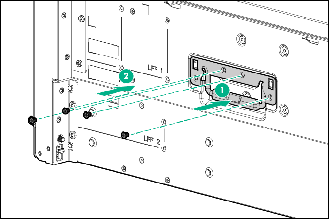
  19. Install the rack server handles.
    Installing the rack server handles
  20. Install the fan cage.
  21. Install the air baffle.
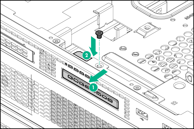
  22. Install the SID blank.
    Installing the SID blank
  23. Install the access panel.
  24. Install the server onto the rack rails, and then slide the assembly into the rack.
    NOTE: For detailed instructions on installing the server into the rack, see the Quick Deploy Rail System Installation Instructions included with the kit.
  25. Connect peripheral devices to the server. For information on identifying connectors, see "Rear panel components."
    WARNING: To reduce the risk of electric shock, fire, or damage to the equipment, do not plug telephone or telecommunications connectors into RJ-45 connectors.
  26. Connect the power cord to the rear of the server.
  27. Connect the power cord to the power source.
    WARNING: To reduce the risk of electric shock or damage to the equipment:
    • Do not disable the power cord grounding plug. The grounding plug is an important safety feature.
    • Plug the power cord into a grounded (earthed) electrical outlet that is easily accessible at all times.
    • Unplug the power cord from the power supply to disconnect power to the equipment.
    • Do not route the power cord where it can be walked on or pinched by items placed against it. Pay particular attention to the plug, electrical outlet, and the point where the cord extends from the server .

Results