x4 Redundant Power Supply backplane option

The x4 Redundant Power Supply backplane option must be installed when more that 3 SFF drive cages (including an NVMe Express bay) are used.

WARNING: When the x4 RPS kit is installed, the number of power supplies installed depends on the preferred configuration. For more information, see "Power supply modes."

To install the component:

Procedure

  1. Back up all server data.
  2. Do one of the following:
  3. Power down the server.
  4. Remove all power:
    1. Disconnect each power cord from the power source.
    2. Disconnect each power cord from the server .
  5. Do one of the following:
  6. Remove the access panel.
  7. Remove the air baffle.
  8. Remove the fan cage.
  9. Disconnect all cables connected to the expansion boards and remove all expansion boards.
  10. Disconnect all cables from the system board.
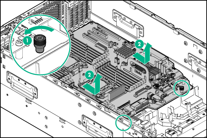
  11. Remove the system board:
    1. Loosen the two system board thumbscrews.
    2. Using the system board tray handles, slide the tray forward, and then remove the system board.
      Removing the system board
  12. Remove all power supplies.
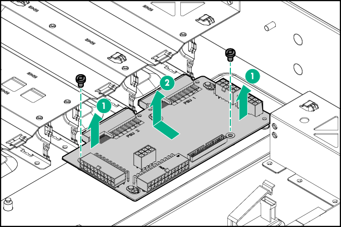
  13. Remove the two bay power supply backplane:
    1. Disconnect all cables connected to the power supply backplane.

      Retain all the cables for reconnecting them to the x4 RPS backplane.

    2. Remove the two screws securing the backplane to the chassis.
    3. Slide the backplane towards the rear of the server, and then lift and remove the backplane.
      Removing the two bay power supply backplane
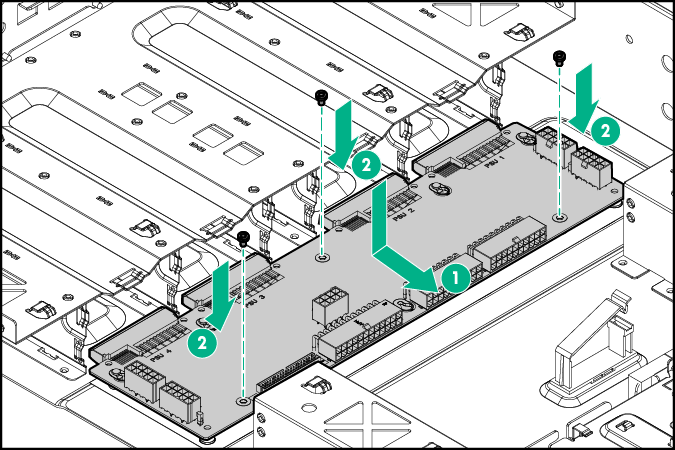
  14. Install the four-bay power supply backplane board:
    1. Align the backplane to the pins on the chassis.
    2. Slide the backplane towards the front of the server.
    3. Tighten the three screws on the backplane.
      Installing the four-bay power supply backplane
  15. Connect all cables to the x4 RPS backplane board.
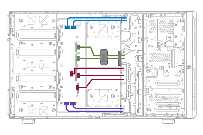
  16. Route the x4 RPS backplane cables.
    x4 Redundant power supply backplane cabling
  17. Install the system board.
  18. Connect all the cables disconnected from the system board.
  19. Install the expansion boards.
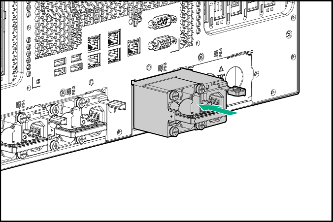
  20. Remove the cover over power supply slots 3 and 4.
    Removing the power supply cover from the power supply slots
  21. Install all power supplies.

    Install a power supply blank into any unpopulated power supply bays.

    Installing the power supply
  22. Install the fan cage.
  23. Install the air baffle.
  24. Install the access panel.
  25. Do one of the following:
    • If the server is in a tower configuration, return the server to an upright position.
    • If the server is in a rack configuration, slide the server into the rack.
  26. Connect each power cord to the server .
  27. Connect each power cord to the power source.
  28. Power up the server.
  29. Do one of the following:

Results