|
|
|


PCIe/FlexibleLOM riser options
I/O modules are specific to each server and are installed in the rear of the chassis. For more information about product features, specifications, options, configurations, and compatibility, see the product QuickSpecs on the Hewlett Packard Enterprise website.
To install the component:
- Power down the server associated with the I/O module.
- Remove the server associated with the I/O module.
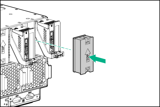
- If an I/O module blank is not installed in the associated even-numbered I/O module bay, install an I/O module blank in the associated even-numbered bay.
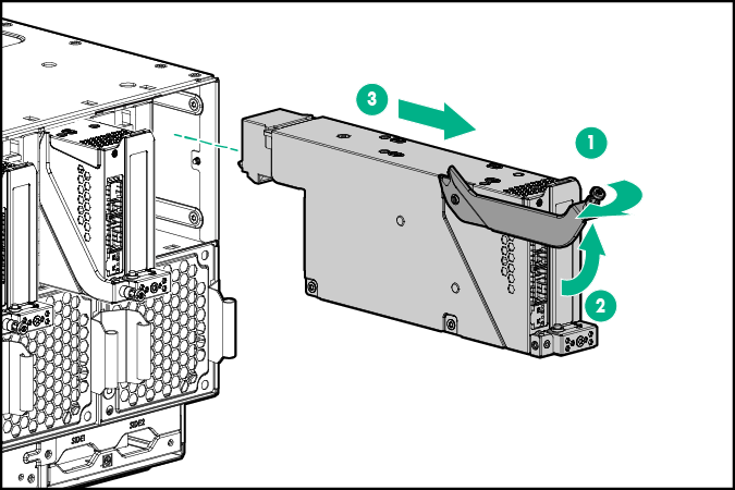
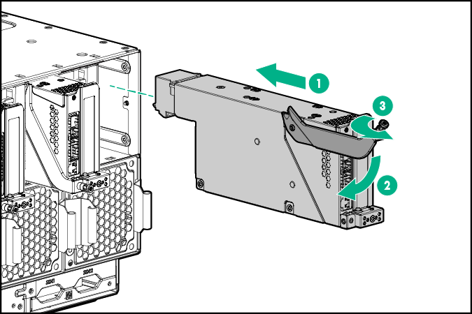
- Remove the PCIe/FlexibleLOM I/O module.
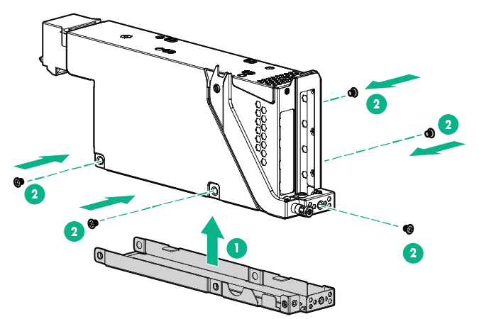
- Remove the cover from the PCIe/FlexibleLOM I/O module.
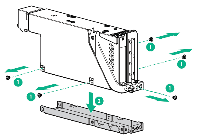

CAUTION: For proper cooling, be sure each I/O module slot has either a blank or a board installed.
- Remove the PCIe slot cover from the slot where the option will be installed.
- Slot 1
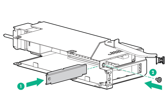
- Slot 2
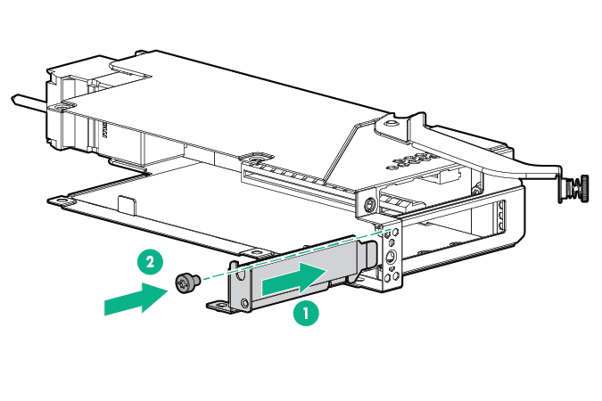
- Slot 1
- Perform the appropriate steps below according to the options you are installing:
- Install the FlexibleLOM adapter in the FlexibleLOM slot on the PCIe/FlexibleLOM riser. To locate the correct slot for the FlexibleLOM, see "I/O module slot definitions."
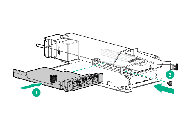
- Install the PCIe expansion board option on the PCIe/FlexibleLOM riser. To locate the correct slot for the PCIe expansion board option, see "I/O module slot definitions."
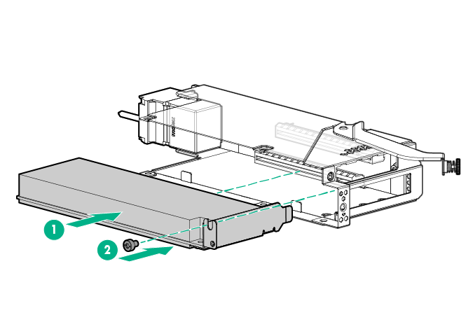
- Install the FlexibleLOM adapter in the FlexibleLOM slot on the PCIe/FlexibleLOM riser. To locate the correct slot for the FlexibleLOM, see "I/O module slot definitions."
- Install the cover on the PCIe/FlexibleLOM I/O module.
- Install the PCIe/FlexibleLOM I/O module.
- Install the server into the chassis.
- Connect all peripheral cables to the server.
- Press the Power On/Standby button.
The server exits standby mode and applies full power to the system. The system power LED changes from amber to green.