|
|
|


12-bay LFF hot-plug drive enablement option
This section provides instructions for installing the 4-bay LFF hot-plug drive cage backplane option, which converts the 8-bay LFF hot-plug drive configuration to a 12-bay LFF hot-plug drive model. This hardware option might require a power supply with a higher wattage rating. To accurately estimate the power consumption of your server and select the appropriate power supply and other system components, see the Hewlett Packard Enterprise Power Advisor website.
To maintain optimal thermal conditions when installing a P-series Smart Array Controller in a 12-bay LFF drive configuration, Hewlett Packard Enterprise recommends the following guidelines:
- When installing only one controller board, install the board in slot 2 of either the 2-slot or the 3-slot PCI riser cage assembly installed in the primary PCIe riser location.
- When installing two controller boards, install the controller boards in slots 2 and 3 of the 3-slot PCI riser cage assembly installed in the primary PCIe riser location.
For more information about product features, specifications, options, configurations, and compatibility, see the product QuickSpecs on the Hewlett Packard Enterprise website.
To install the component:
- Power down the server.
- Remove all power:
- Disconnect each power cord from the power source.
- Disconnect each power cord from the server.
- Do one of the following:
- If installed, remove the security bezel.
- Remove the access panel.
- Use a flathead screwdriver to carefully pry the blanks from the box 1 drive bays 1-4.
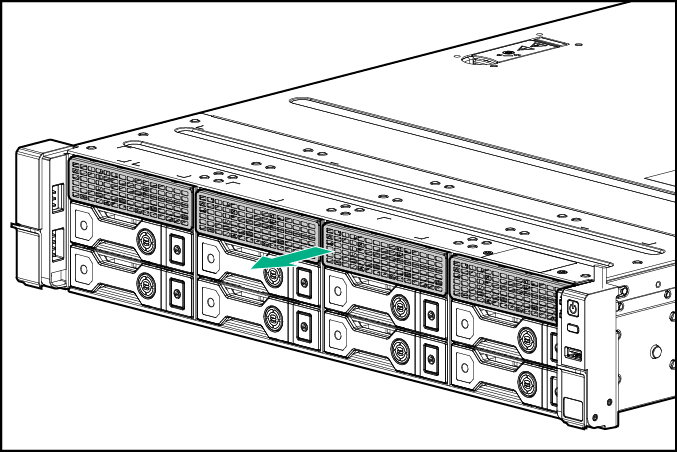
Retain the blanks for future use.
- Remove the primary PCI riser cage.
- Remove the air baffle.
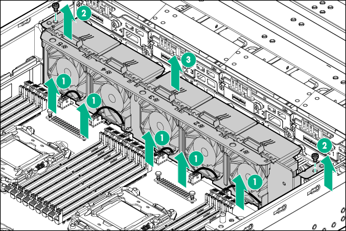
- Disconnect the fan cables.
- Remove the fan cage.
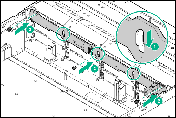
- Install the 4-bay LFF hot-plug drive cage backplane:
- Insert the guide tabs on the rear of the cage into the corresponding backplane slots.
- Secure the backplane with the three screws.
- Install the fan cage.
- Connect the fan cables.
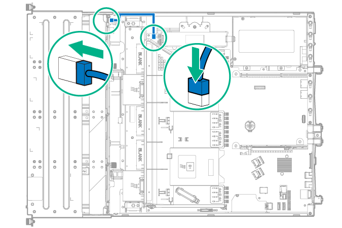
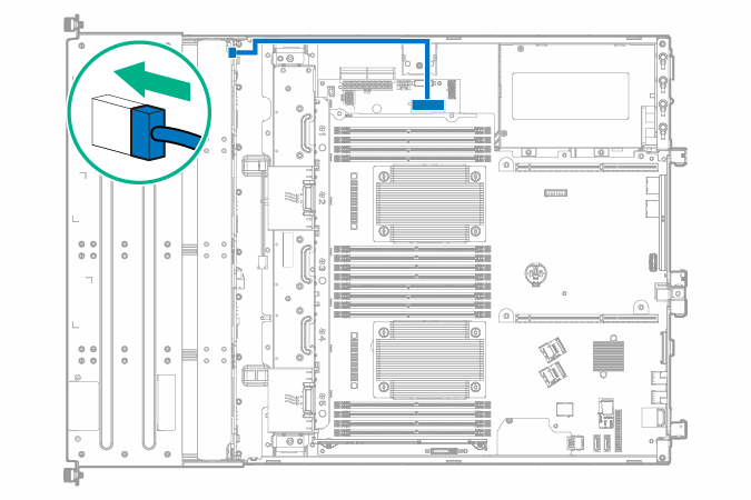
- Connect the 12-bay LFF drive identification signal cable to the 8-bay LFF hot-plug drive cage backplane, and then to the system board.
- Connect the BP1 power connector of the LFF power cable to the 4-bay LFF hot-plug drive cage backplane.
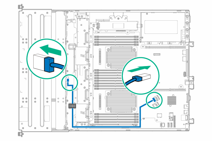
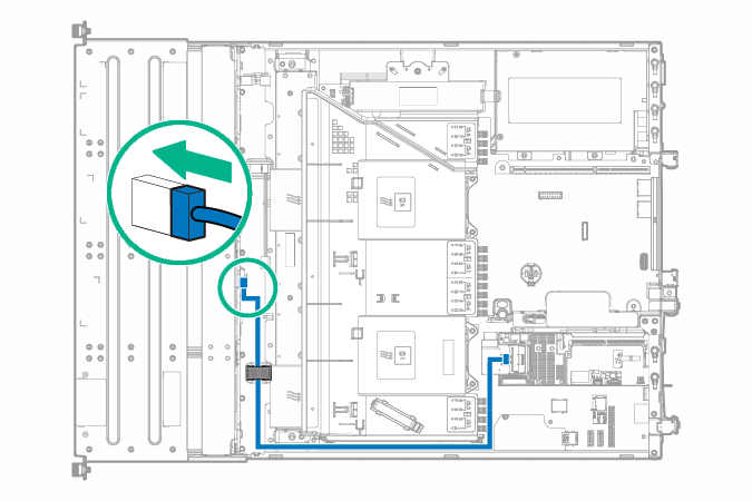
- To connect the 4-bay LFF hot-plug drive backplane to the onboard controller, connect the 520-mm Mini-SAS cable:
- Connect the Mini-SAS cable to the system board.
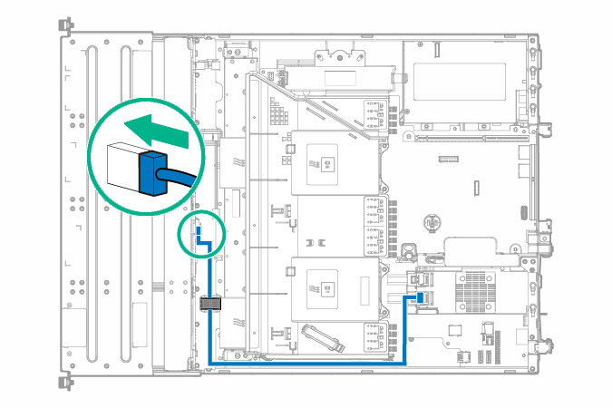
- Route the Mini-SAS cable along the side of the system board towards the front chassis, and then connect the cable to the drive backplane.
- Secure the Mini-SAS cable in the right front chassis cable clip.
- Install the air baffle.
- Install the primary PCI riser cage.
- To connect the 4-bay LFF hot-plug drive backplane to an HBA option, connect the 540-mm Mini-SAS cable:
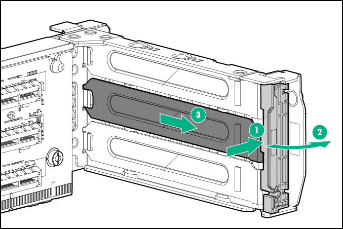
- Identify the riser slot compatible with the new option, and then remove the cover opposite from that slot.
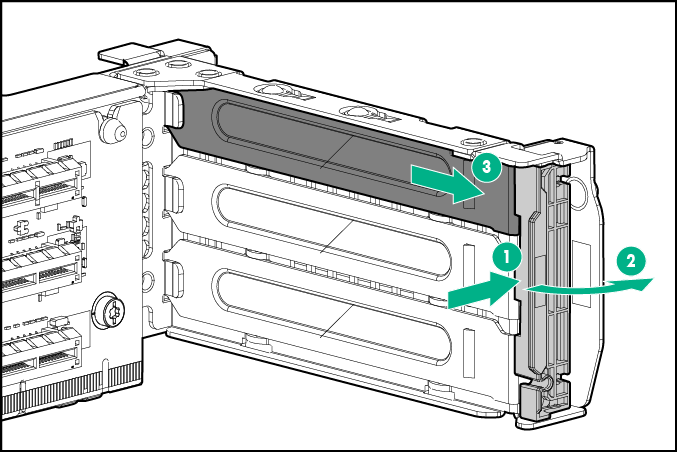
- Install the HBA. Verify that the board is firmly seated in the slot.
For more information about the HBA and its features, select the relevant user documentation on the Hewlett Packard Enterprise website.
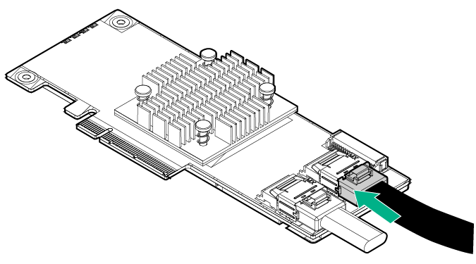
- Connect the Mini-SAS cable to the HBA.
- Install the air baffle.
- Install the primary PCI riser cage.
- Route the Mini-SAS cable along the side of the system board towards the front chassis, and then connect the cable to the drive backplane.
- Secure the Mini-SAS cable in the right front chassis cable clip.
- Identify the riser slot compatible with the new option, and then remove the cover opposite from that slot.
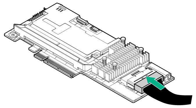
- To connect the 4-bay LFF hot-plug drive backplane to an HPE Smart Array P-series Controller option, connect the 540-mm Mini-SAS cable:
- Identify the riser slot compatible with the new option, and then remove the cover opposite from that slot.
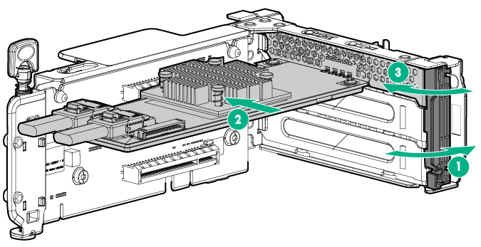
- Install the storage controller. Verify that the board is firmly seated in the slot.
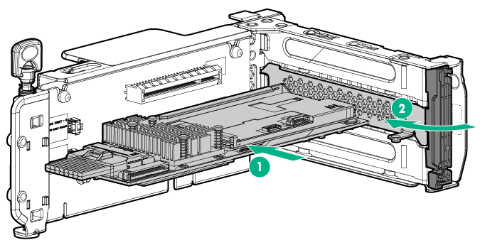
For more information about the integrated storage controller and its features, select the relevant user documentation on the Hewlett Packard Enterprise website.
- Connect the Mini-SAS cable to the storage controller.
- Install the air baffle.
- Install the primary PCI riser cage.
- Route the Mini-SAS cable along the side of the system board towards the front chassis, and then connect the cable to the drive backplane.
- Secure the Mini-SAS cable in the right front chassis cable clip.
- Identify the riser slot compatible with the new option, and then remove the cover opposite from that slot.
- Install the access panel.
- If removed, install the security bezel.
- Do one of the following:
- Slide the server into the rack.
- Install the server into the rack.
- Power up the server.
- Install the drives.