|
|
|


System board
|
WARNING: To reduce the risk of personal injury, electric shock, or damage to the equipment, remove the power cord to remove power from the server. Pressing the Power On/Standby button does not shut off system power completely. Portions of the power supply and some internal circuitry remain active until AC power is removed. |
To remove the component:
- Power down the server.
- Remove all power:
- Disconnect each power cord from the power source.
- Disconnect each power cord from the server.
- Extend the server from the rack.
- Remove all power supplies.
- Remove the access panel.
- Depending on the server options installed, do one of the following:
- Remove the primary PCI riser cage.
- If installed, remove the secondary PCIe riser cage.
- Remove the Smart Storage Battery.
- Remove the FlexibleLOM.
- Remove all DIMMs.
- Remove the power supplies.
- Remove the power supply backplane.
- Disconnect all cables connected to the system board.
- Remove the heatsink.
- Remove the processor.
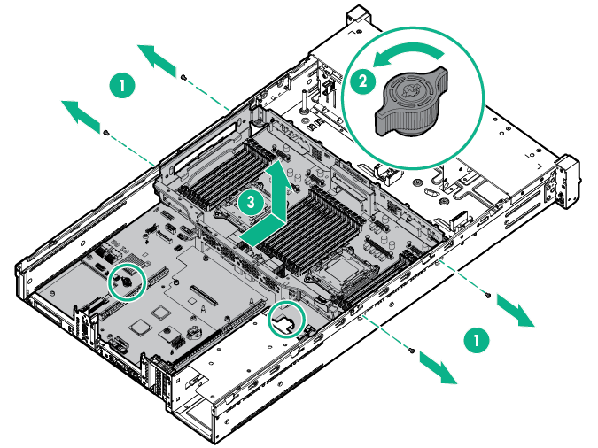
- Remove the system board.
To replace the component:
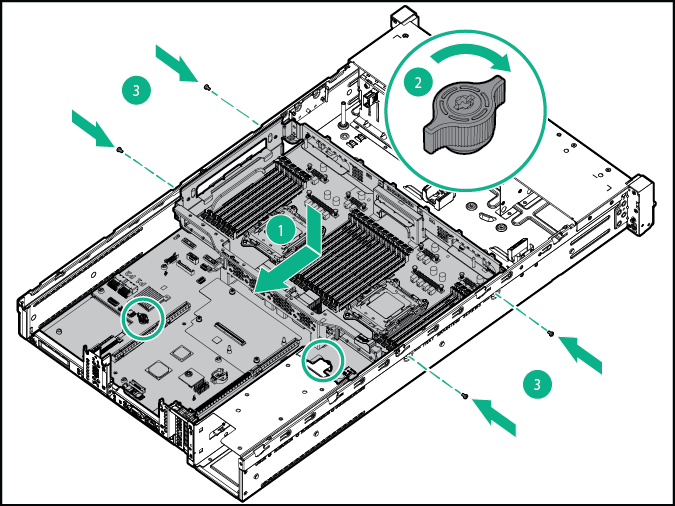
- Install the spare system board.
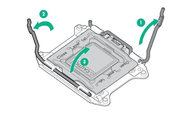
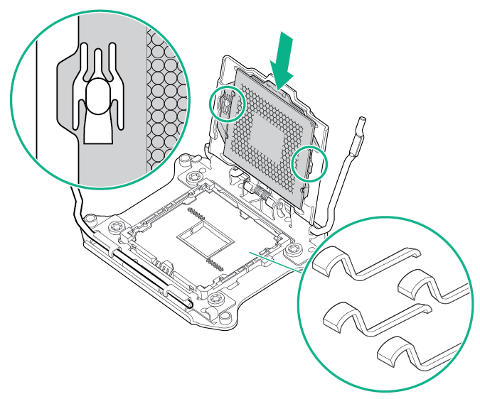
- Open each of the processor locking levers in the order indicated in the following illustration, and then open the processor retaining bracket.
- Remove the clear processor socket cover. Retain the processor socket cover for future use.
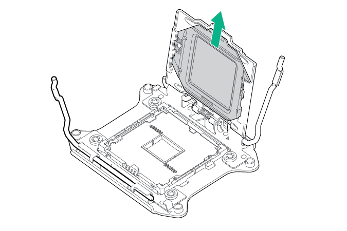

CAUTION: THE PINS ON THE SYSTEM BOARD ARE VERY FRAGILE AND EASILY DAMAGED. To avoid damage to the system board, do not touch the processor or the processor socket contacts.
- Install the processor. Verify that the processor is fully seated in the processor retaining bracket by visually inspecting the processor installation guides on either side of the processor. THE PINS ON THE SYSTEM BOARD ARE VERY FRAGILE AND EASILY DAMAGED.
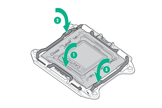
- Close the processor retaining bracket. When the processor is installed properly inside the processor retaining bracket, the processor retaining bracket clears the flange on the front of the socket.
CAUTION: Do not press down on the processor. Pressing down on the processor may cause damage to the processor socket and the system board. Press only in the area indicated on the processor retaining bracket.
CAUTION: Close and hold down the processor cover socket while closing the processor locking levers. The levers should close without resistance. Forcing the levers closed can damage the processor and socket, requiring system board replacement.
- Press and hold the processor retaining bracket in place, and then close each processor locking lever. Press only in the area indicated on the processor retaining bracket.
- Install the processor socket cover onto the processor socket of the failed system board.
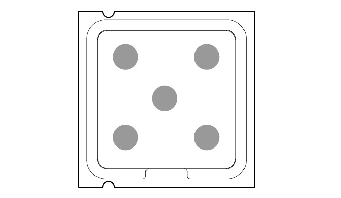
- Clean the old thermal grease from the heatsink and the top of the processor with the alcohol swab. Allow the alcohol to evaporate before continuing.
- Apply all the grease to the top of the processor in the following pattern to ensure even distribution.
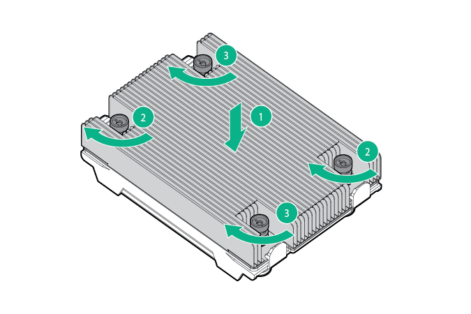
- Install the heatsink.

IMPORTANT: Install all components with the same configuration that was used on the failed system board.
- Install all components removed from the failed system board.
- Install the access panel.
- Install the power supplies.
- Power up the server.
After you replace the system board, you must re-enter the server serial number and the product ID.
- During the server startup sequence, press the F9 key to access RBSU.
- Select the Advanced Options menu.
- Select Service Options.
- Select Serial Number. The following warnings appear:
WARNING! WARNING! WARNING! The serial number is loaded into the system during the manufacturing process and should NOT be modified. This option should only be used by qualified service personnel. This value should always match the serial number sticker located on the chassis.
Warning: The serial number should ONLY be modified by qualified personnel. This value should always match the serial number located on the chassis.
- Press the Enter key to clear the warning.
- Enter the serial number and press the Enter key.
- Select Product ID. The following warning appears:
Warning: The Product ID should ONLY be modified by qualified personnel. This value should always match the Product ID on the chassis.
- Enter the product ID and press the Enter key.
- Press the Esc key to close the menu.
- Press the Esc key to exit RBSU.
- Press the F10 key to confirm exiting RBSU. The server automatically reboots.