|
|
|


Processor
|
WARNING: To reduce the risk of personal injury from hot surfaces, allow the drives and the internal system components to cool before touching them. |
|
WARNING: To reduce the risk of personal injury, electric shock, or damage to the equipment, remove the power cord to remove power from the server. Pressing the Power On/Standby button does not shut off system power completely. Portions of the power supply and some internal circuitry remain active until AC power is removed. |
|
CAUTION: To prevent possible server malfunction and damage to the equipment, multiprocessor configurations must contain processors with the same part number. |
|
IMPORTANT: Processor socket 1 must be populated at all times or the server does not function. |
To remove the processor:
- Power down the server.
- Remove all power:
- Disconnect each power cord from the power source.
- Disconnect each power cord from the server.
- Extend the server from the rack.
- Remove the processor memory drawer.
- Remove the processor memory drawer cover.
- Remove the heatsink.
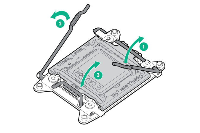
- Open each of the processor locking levers in the order indicated, and then open the processor retaining bracket.
- Remove the processor from the processor retaining bracket.
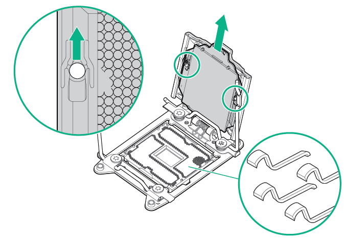

CAUTION: To avoid damage to the processor, do not touch the bottom of the processor, especially the contact area.
To replace the component:
- Install the processor. Verify that the processor is fully seated in the processor retaining bracket by visually inspecting the processor installation guides on either side of the processor. THE PINS ON THE SYSTEM BOARD ARE VERY FRAGILE AND EASILY DAMAGED.
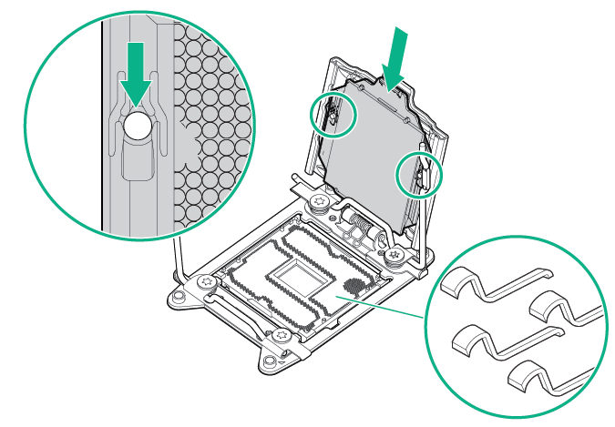
CAUTION: THE PINS ON THE SYSTEM BOARD ARE VERY FRAGILE AND EASILY DAMAGED. To avoid damage to the system board, do not touch the processor or the processor socket contacts.
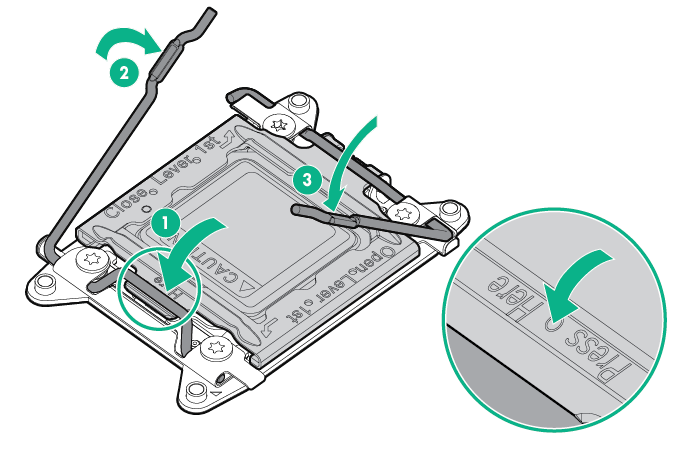
- Close the processor retaining bracket. When the processor is installed properly inside the processor retaining bracket, the processor retaining bracket clears the flange on the front of the socket.
CAUTION: Do not press down on the processor. Pressing down on the processor might damage the processor socket and the system board. Press only in the area indicated on the processor retaining bracket.
- Press and hold the processor retaining bracket in place, and then close each processor locking lever. Press only in the area indicated on the processor retaining bracket.
- Remove the thermal interface protective cover from the heatsink.
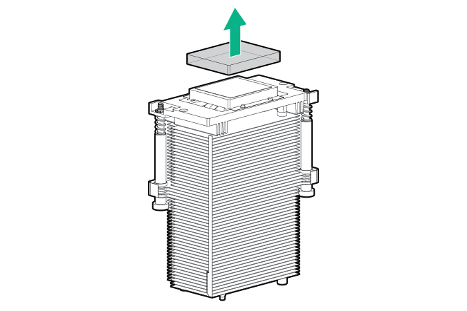
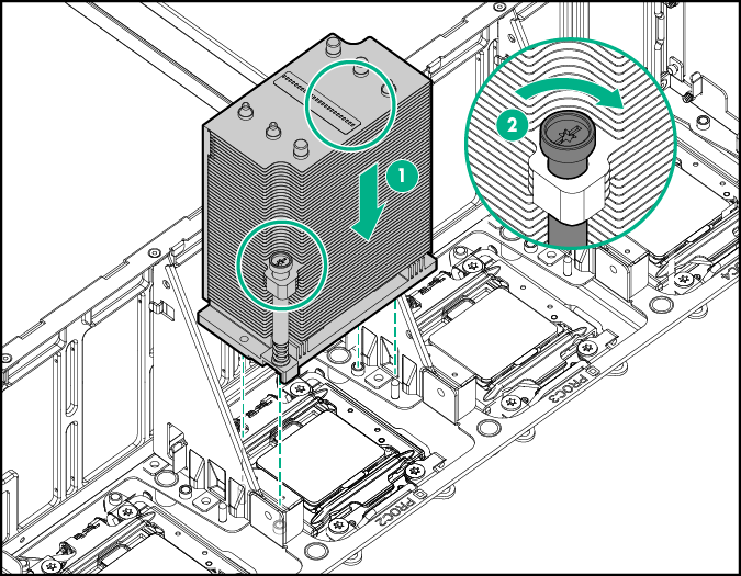
CAUTION: To prevent the heatsink from tilting to one side during installation and removal procedures, use a diagonally opposite pattern (an “X” pattern) when loosening and tightening the two spring-loaded screws. To prevent the screws from breaking off, do not over-tighten the screws. A maximum torque of 0.45 N m (4 in-Ib) is set for the system.
- Install the heatsink.
- Install the processor memory drawer cover.
- Install the processor memory drawer.
- Connect each power cord to the server.
- Connect each power cord to the power source.
- Power up the server.