Installing the HPE NVMe Express bay

The Express bay option includes a 6 NVMe SSD Express bay drive cage backplane and an Express bay bridge card.

An x4 Redundant Power Supply kit is required when four or more drive cages, including the Express bay drive kit, are installed in the server.

The Express drive bay supports 400 GB, 800 GB, 1.2 TB NVMe SSD drives. The HPE NVMe Express drive bay may be installed in bay 1 or 4 of an SFF model.

For more information about NVMe SSDs, see the Hewlett Packard Enterprise website.

For more information on supported drives, see the Hewlett Packard Enterprise website.

CAUTION: To prevent damage to electrical components, take the appropriate anti-static precautions before beginning any system installation. Improper grounding can cause electrostatic discharge.

To install the option:

Procedure

  1. Back up all server data.
  2. Do one of the following:
  3. Power down the server.
  4. Remove all power:
    1. Disconnect each power cord from the power source.
    2. Disconnect each power cord from the server .
  5. Do one of the following:
  6. Remove the access panel.
  7. Remove the air baffle.
  8. Remove the fan cage.
  9. Install the Express bay drive cage assembly:
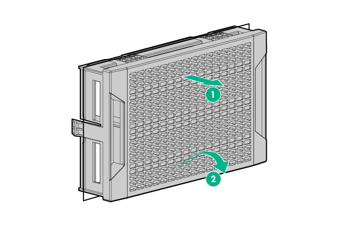
    1. Remove the drive cage blank from box 1 or 4.
      Removing the drive box blank (SFF)
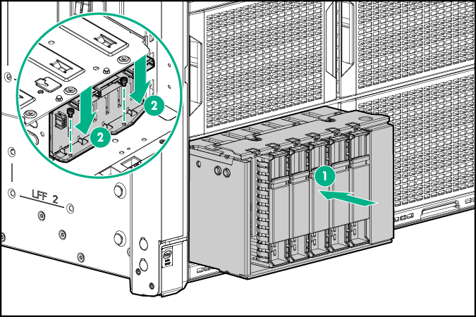
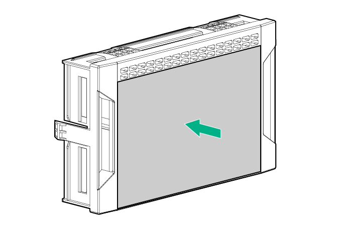
    2. Install the Express bay drive cage and backplane assembly.
      Installing the 6 Express bay SFF drive cage
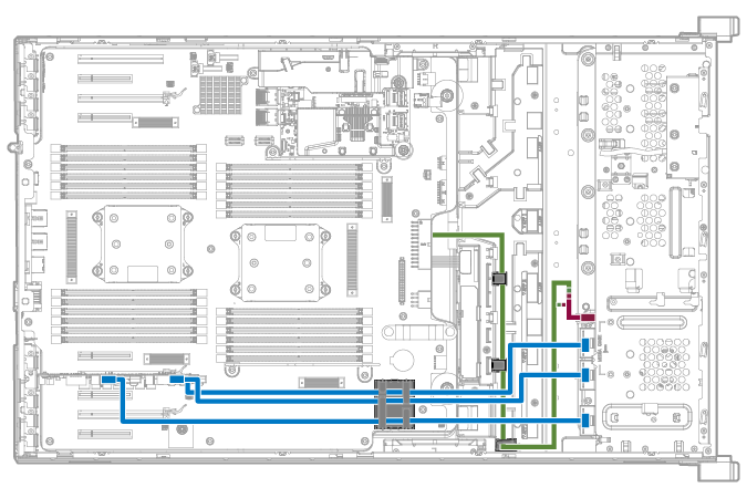
    3. Connect the 2x4 connector of the power Y-cable to the Express bay drive cage backplane.
    4. Connect the other two ends of the power Y-cable to the cable connectors from the server power supply backplane.
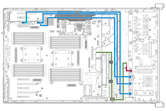
    5. Connect the three Express bay data cables to the Express bay drive cage backplane.
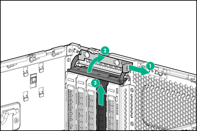
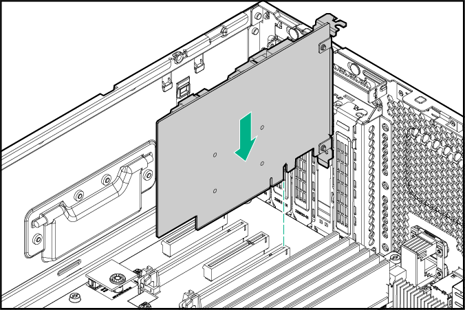
  10. Install the Express bay bridge card in PCIe slot 3, 6, or 8:
    NOTE: A second processor must be installed if the Express bay bridge card is installed in PCIe slot 6 or 8.
    1. Remove the expansion slot retainer cover and the slot blank.
      Removing the slot cover retainer and slot blank
    2. Install the Express bay bridge card.
      Installing the 6 hard drive switch card
    3. Close the PCI slot cover retainer.
    4. Connect the Express bay data cables to the corresponding ports on the Express bay bridge card.
      • Cable routing if the Express bay bridge card is installed in PCIe slot 3
        Connecting the switch card and power supply backplane cables
      • Cable routing if a second processor is installed and the express bay bridge card is installed in PCIe slot 6 or 8
        Connecting the switch card and power supply backplane cables
  11. To ensure proper thermal cooling, adhere airflow covers to the outside of all drive cage blanks.
    1. Remove all drive cage blanks.
    2. Install an airflow cover onto each drive cage blank, leaving only the top two rows of venting exposed.
      Installing an airflow cover onto each drive cage blank
    3. Install the drive cage blanks.
  12. Install the NVMe SSD drives.
  13. Install the fan cage.
  14. Install the air baffle.
  15. Install the access panel.
  16. Do one of the following:
    • If the server is in a tower configuration, return the server to an upright position.
    • If the server is in a rack configuration, slide the server into the rack.
  17. Connect each power cord to the server .
  18. Connect each power cord to the power source.
  19. Power up the server.
  20. Do one of the following:

Results