Installing a storage controller and FBWC module option

NOTE: Smart Array controllers are not supported in PCIe slot 5.

An HPE Smart Array Controller Mini-SAS cable option is required to install a Smart Array Controller option.

To install the component:

Procedure

  1. Back up all server data.
  2. Do one of the following:
  3. Power down the server.
  4. Remove all power:
    1. Disconnect each power cord from the power source.
    2. Disconnect each power cord from the server .
  5. Do one of the following:
  6. Remove the access panel.
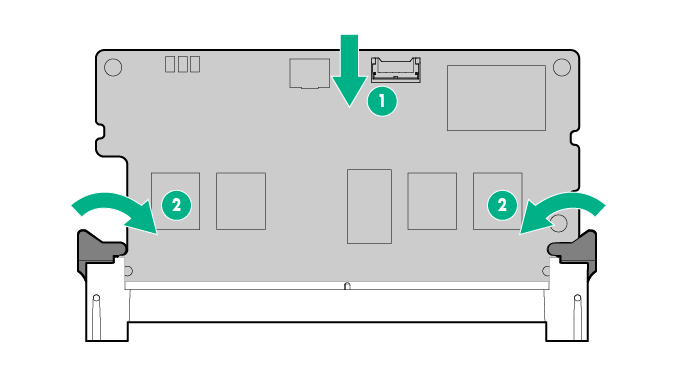
  7. If you intend to use an FBWC module, install the module on the storage controller. Depending on the controller model, the cable connector on the cache module might be facing up or down when the module is installed on the controller board.
    1. Connect the cache module backup power cable to the module.
      Connecting the cache module backup power cable to the module
    2. Install the cache module on the storage controller.
      Installing the FBWC module on the storage controller option
  8. Install the Smart Array controller.
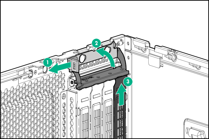
    1. Select an available expansion slot from PCIe slots 1 to 4 or 6 to 9, and then remove the slot cover of the corresponding slot.

      If installing the HBA in slots 6-9, a second processor option must be installed first. See "Processor option."

      Removing the slot blank
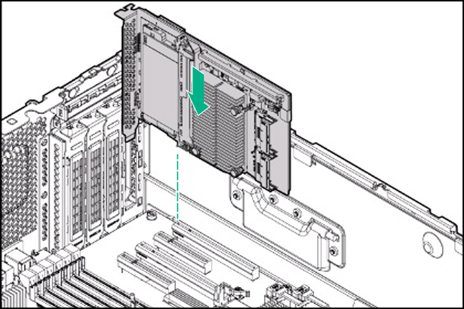
    2. Install the Smart Array controller. Verify that the board is firmly seated in the slot.
      Installing the P840 controller board
  9. Close the slot retainer or tighten the screw to secure the controller.
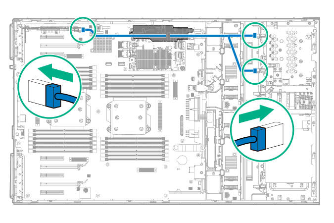
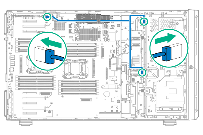
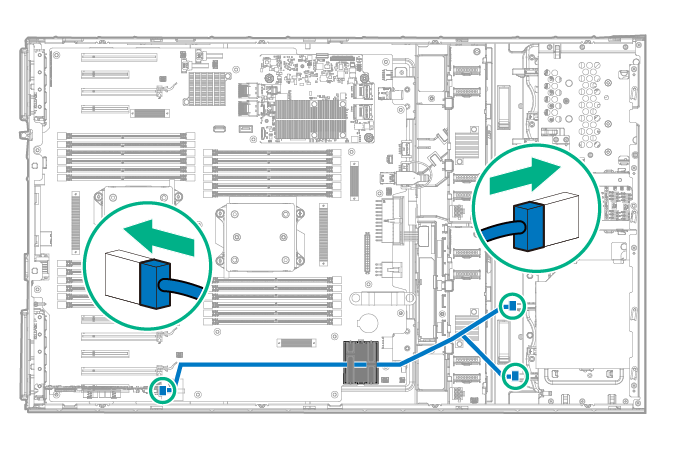
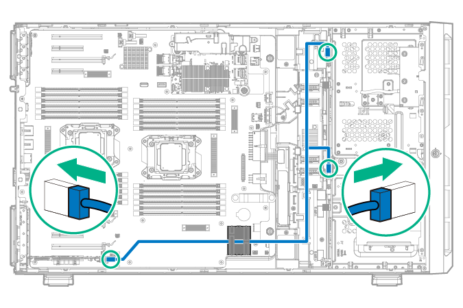
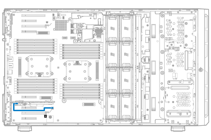
  10. Connect the Mini-SAS Y-cable:
    1. Connect the common end of the Mini-SAS Y-cable to the Smart Array controller.
    2. Route the two ends of the Mini-SAS Y-cable through the cable management clips, and then connect them to the drive backplane.
    • Cable routing if the Smart Array controller is installed in PCIe slot 1 to 4
      • SFF configuration
        Mini-SAS Y-cable routing for PCIe slot 1 to 4 (SFF configuration)
      • LFF configuration
        Mini-SAS Y-cable routing for PCIe slot 1 to 4 (LFF configuration)
    • Cable routing if a second processor is installed and the Smart Array controller is installed in PCIe slot 6 to 9
      • SFF configuration
        Mini-SAS Y-cable routing for PCIe slot 6 to 9 (SFF configuration)
      • LFF configuration
        Mini-SAS Y-cable routing for PCIe slot 6 to 9 (LFF configuration)
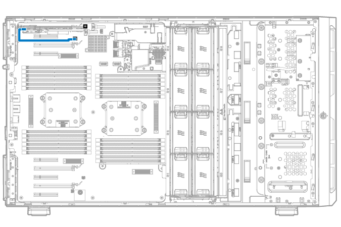
  11. If the cache module is installed on the Smart Array controller, connect the cache module backup power cable to the system board.

    There are two FBWC module backup power cable connectors available for each group of PCIe connectors.

    • Backup power cabling when the Smart Array controller is installed in PCIe slot 1 to 4
      Storage controller backup power cabling when controller is installed in slot 1 to 4
    • Backup power cabling when the Smart Array controller is installed in PCIe slot 6 to 9
      Storage controller backup power cabling when controller is installed in slot 6 to 9
  12. If you are planning to install the Smart Storage Battery, install it now.
  13. Install the fan cage.
  14. Install the air baffle.
  15. Install the access panel.
  16. Do one of the following:
    • If the server is in a tower configuration, return the server to an upright position.
    • If the server is in a rack configuration, slide the server into the rack.
  17. Connect each power cord to the server .
  18. Connect each power cord to the power source.
  19. Power up the server.
  20. Do one of the following:

Results

For more information on the Smart Array storage controllers, select the relevant user documentation on the Hewlett Packard Enterprise website.

To configure arrays, see the HPE Smart Storage Administrator User Guide on the Hewlett Packard Enterprise website.