Replacing the system board module

WARNING: To reduce the risk of personal injury from hot surfaces, allow the drives and the internal system components to cool before touching them.
CAUTION: To prevent damage to electrical components, properly ground the server before beginning any installation procedure. Improper grounding can cause electrostatic discharge.
Procedure
  1. Back up all server data.
  2. Power down the server (Power down the server).
  3. Disconnect all peripheral cables from the server.
  4. Remove the system board module from the chassis (Removing the system board module from the chassis).
  5. Place the tray on a flat, level work surface.
  6. Remove the riser cage (Removing the riser cage).
  7. Remove the M.2 riser board (Removing and replacing the M.2 SSD riser board).
  8. Remove the type -a controller (Removing and replacing a type -a controller).
  9. Remove the FlexibleLOM adapter (Removing and replacing the FlexibleLOM).
  10. Remove all DIMMs (Removing and replacing a DIMM).
  11. Disconnect all cables connected to the system board.
  12. Observe the following cautions.
    CAUTION: Be sure to loosen each heatsink nut in the order indicated. Otherwise, damage might occur to the heatsink or processor.
    CAUTION: Install the processor heatsink assembly as soon as possible after removing it. Do not leave the processor socket unpopulated for extended periods of time.
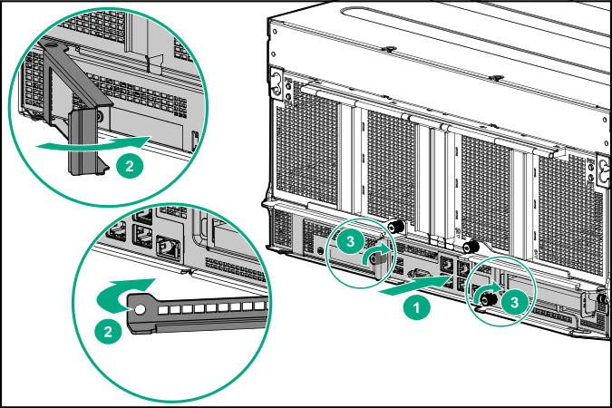
  13. Remove the processor heatsink assembly:
    1. Allow the heatsink to cool.
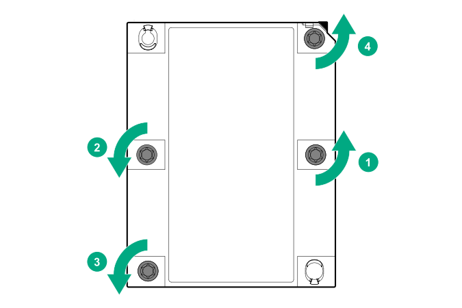
    2. Using a T-30 Torx screwdriver, loosen the heatsink nuts.

      Removing the processor heatsink assembly
    3. Lift the processor heatsink assembly up and away from the system board.

Installing components into the new system board module

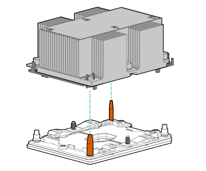
  1. Install the processor heatsink assembly:
    1. Locate the Pin 1 indicator on the processor carrier and the socket.
    2. Align the processor heatsink assembly with the heatsink alignment pins, and then gently lower it down until it sits evenly on the socket.
      The heatsink alignment pins are keyed. The processor heatsink assembly will only install one way.

      Your heatsink may look different than the one shown.


      Installing the processor heatsink assembly
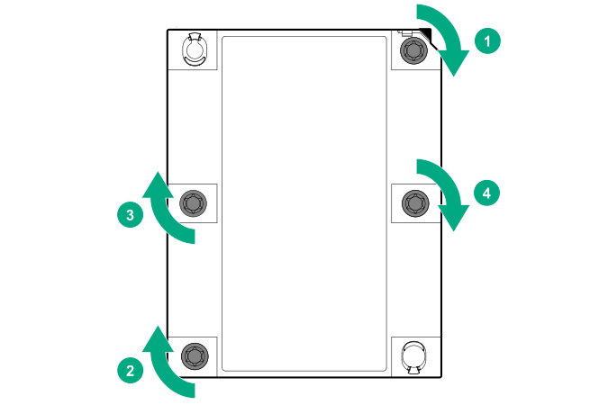
    3. Using a T-30 Torx screwdriver, fully tighten each heatsink nut until it no longer turns.
      CAUTION: Be sure to tighten each heatsink nut fully in the order indicated. Otherwise, boot failure or intermittent shutdowns might occur.

      Tightening the heatsink nuts
  2. Install all components removed from the failed system board module.
    IMPORTANT: Install all components with the same configuration that was used on the failed system board.
  3. Install the system board module into the chassis.
  4. Power up the server.
  5. Ensure all firmware, including option cards and embedded devices, is updated to the same versions to ensure that the latest drivers are being used.
  6. Re-enter any Secure Boot Keys that were previously added in the Secure Boot configuration.
  7. Re-enter the server serial number and the product ID (Re-entering the server serial number and product ID).
  8. If PCIe GPU cards are installed in the server, reconfigure the PCIe GPU slots (Configuring PCIe GPU slots).