HPE Apollo 6500 Gen10 System/HPE ProLiant XL270d Gen10 Server User Guide
Component identification
Front panel components
Front panel LEDs and buttons
UID button functionality
Front panel LED power fault codes
Rear panel components (SXM2 GPU module)
Rear panel components (PCIe GPU module)
System board components
System maintenance switch descriptions
NMI functionality
DIMM slot locations
DIMM label identification
SXM2 GPU module components
PCIe GPU module components
Power distribution board and bus bar components
Power supply LED
Fan module numbering
Supported drives
Hot-plug drive LED definitions
NVMe SSD LED definitions
Operations
Power up the server
Power down the server
Extending the chassis from the rack
Removing the GPU tray from the chassis
Removing the system board module from the chassis
Removing the access panel
Removing the fan cage
Removing the riser cage
Setup
Safety and regulatory compliance
Optional service
Warnings and cautions
Determining power and cooling configurations
Power requirements
Hot-plug power supply calculations
Connecting a DC power cable to a DC power source
Optimum environment
Space and airflow requirements
Temperature requirements
Electrical grounding requirements
Identifying the contents of the shipping carton
Installation overview
Installing the chassis into the rack
Installing the rails and the cable management arm
Installing hardware options
Operating system
Installing the operating system with Intelligent Provisioning
Selecting boot options in UEFI Boot Mode
Selecting boot options
Registering the server
Hardware options installation
Hewlett Packard Enterprise product QuickSpecs
Introduction
Installing a power supply
Installing an 8SFF drive cage
Installing a hot-plug SAS or SATA drive
Installing the NVMe enablement kit
Installing NVMe drives
Installing the M.2 SSD enablement option
Memory options
DIMM slot locations
DIMM population information
DIMM-processor compatibility
HPE SmartMemory speed information
DIMM label identification
Installing a DIMM
Installing a type -a controller
Installing a type -p controller
PCIe GPU options
Installing a PCIe GPU
SXM2 GPU options
Topology A
Topology B
Topology C
Installing an SXM2 GPU
Installing a PCIe riser board in the SXM2 GPU module
Installing a PCIe riser board in the PCIe GPU module
Installing a processor heatsink assembly
HPE Smart Storage Battery
Installing the HPE Smart Storage Battery
Cabling
SAS/SATA cabling
NVMe cabling
AC power cabling
Drive power cabling
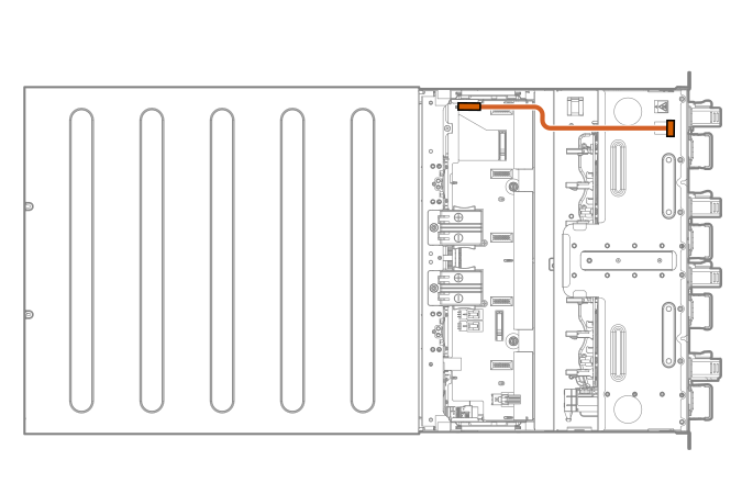
Front LED/power/UID cabling
GPU module power cabling
HPE Smart Storage Battery cabling
Software and configuration utilities
Server mode
Product QuickSpecs
Active Health System Viewer
Active Health System
HPE iLO 5
iLO Federation
iLO Service Port
iLO RESTful API
RESTful Interface Tool
iLO Amplifier Pack
Integrated Management Log
Intelligent Provisioning
Intelligent Provisioning operation
Management Security
Scripting Toolkit for Windows and Linux
UEFI System Utilities
Selecting the boot mode
Secure Boot
Launching the Embedded UEFI Shell
HPE Smart Storage Administrator
HPE InfoSight for servers
USB support
External USB functionality
Redundant ROM support
Safety and security benefits
Keeping the system current
Updating firmware or system ROM
Drivers
Software and firmware
Operating system version support
HPE Pointnext Portfolio
Proactive notifications
Troubleshooting
Troubleshooting resources
Removing and replacing the system battery
Specifications
Chassis mechanical specifications
Power supply specifications
Electrostatic discharge
Preventing electrostatic discharge
Grounding methods to prevent electrostatic discharge
Websites
Support and other resources
Accessing Hewlett Packard Enterprise Support
Accessing updates
Customer self repair
Remote support
Warranty information
Regulatory information
Documentation feedback
Version
Search
Home
Cabling
Front LED/power/UID cabling
Front LED/power/UID cabling
nonav
nonav