Installing a type-p controller
Hewlett Packard Enterprise recommends performing a backup of all server data before installing or removing a controller or adapter.
Population guidelines
Up to four internal cabled controllers can be installed in the primary riser cage.
The butterfly riser supports only two internal cabled controllers in slots 15 and 16.
No internal cabled controllers are supported in slots 8 through 14.
There are no limitations on the number of externally cabled controllers.
Before you perform this procedure, make sure that you have the following items available:
The components included with the hardware option kit
T-10 Torx screwdriver
- To ensure that cables are connected correctly, observe the labels on the cable and component connectors.
- Be sure that you have the latest firmware for the controllers, HBAs, and the expander card. To download the latest firmware, see the Hewlett Packard Enterprise website (http://www.hpe.com/support/hpesc).
To enable SmartCache or CacheCade in the Smart Array controller, be sure that an energy pack is installed.
-
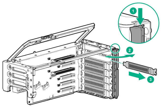
Remove the expansion slot blank from the riser cage.
The primary PCIe riser cage is shown.
-
Install the controller into the PCI riser cage, depending on the server configuration.
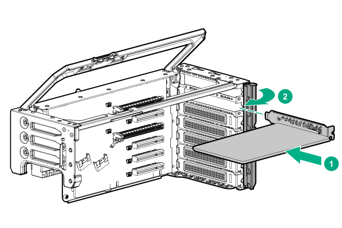
HPE Smart Array SR-series controllers
If your server configuration requires installation of a SAS expander, observe the following:24 drive configuration—Install the SAS controller in slot 6. The SAS expander card must be installed into slot 5 of the primary riser cage.
48 drive configuration—Install the SAS controllers in slots 6 and 16. Install SAS expander cards into slot 5 of the primary riser cage, and into slot 15 of the butterfly riser cage.
HPE Smart Array MR-series controllers24 drive configuration—Install the controller in the primary cage.
48 drive configuration—Install the controllers in the primary and butterfly riser cages.
-
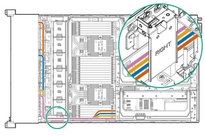
Using the shorter of the two cables provided, connect the controller backup power cable to the controller backup power connector on the riser board (Riser board components).
 IMPORTANT:To enable SmartCache or CacheCade in a P-class type-p Smart Array controller, you must:
Connect the controller backup power cable to the controller backup power connector on the system or riser board.
Connect the energy pack cable to the energy pack connector on the system board.

Item Description1 1 Type-p Smart Array controller connected to the controller backup power connector 2 Energy pack connected to the energy pack connector 1Your server might appear different.
To locate these connectors, see System board components and Riser board components.
-
Route and connect the cables between the storage devices and the controller.
A maximum of four cables can be routed to each riser cage.
CAUTION:To avoid damage to the cables and server components, always route cables flat against the server walls, and separate the cables as they enter the primary riser cage. Bundled cables can be pinched or damaged when installing the fan cage or primary riser cage.