Installing an HPE InfiniBand HDR/Ethernet 940QSFP 56x16 adapter
The server supports installing two adapters in a four-processor configuration and one adapter in a two-processor configuration. Each adapter requires the installation of an auxiliary card in a supported slot.
Use the following table to determine the supported slot locations:
| Processors | Adapter slot | Auxiliary card slot |
|---|---|---|
| 2 | 6 | 13 |
| 4 | 2 | 9 |
| 4 | 11 |
For more information on expansion slot numbering, see Rear panel components.
Before you perform this procedure, make sure that you have the following items available:
The components included with the hardware option kit
T-10 Torx screwdriver
HPE InfiniBand HDR PCIe G3 Auxiliary card with 350mm cable kit
7 slot riser board installed in the primary and secondary riser cages
-
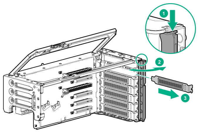
Remove the expansion slot blanks from the required slots.
The primary PCIe riser cage is shown.
-
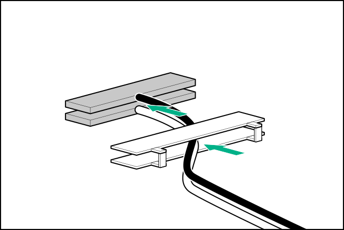
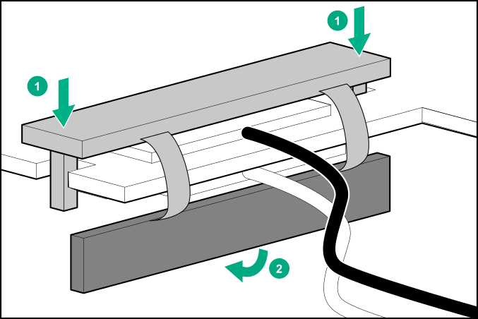
Thread the adapter end of the auxiliary card cables through one of the retention clips provided with the installation kit.
-
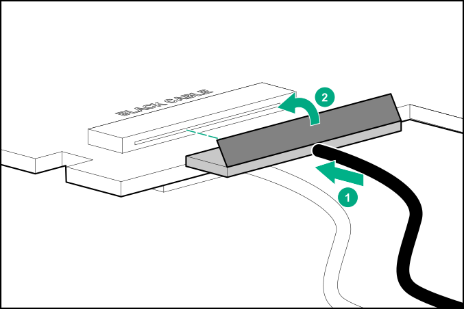
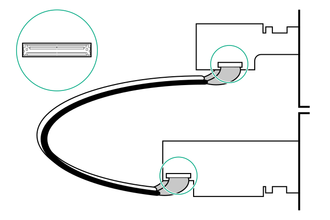
Open the cable latch door, connect the auxiliary card cables to the adapter ports so that the golden side of the cable connector is on the top, and then close the cable latch door.
The white and black cables from the auxiliary card connect to the expansion board ports labeled WHITE CABLE and BLACK CABLE, respectively.
The cable latch door must be open when connecting the cables.
CAUTION:The connector pins are fragile and easily damaged. To avoid damaging the connector pins, do not use excessive force when connecting the cables.
-
Install the retention clip.
-
Confirm that the orientation of the cables is correct.
-
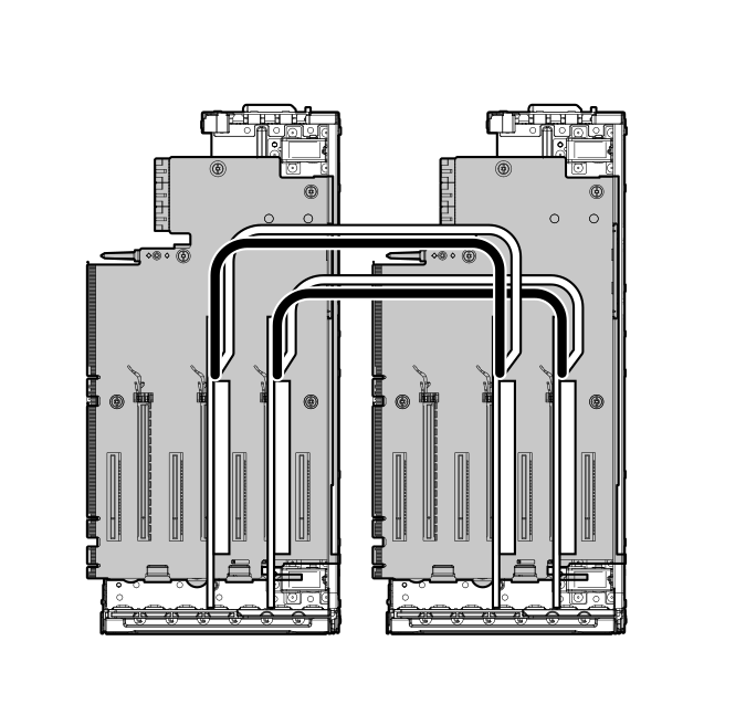
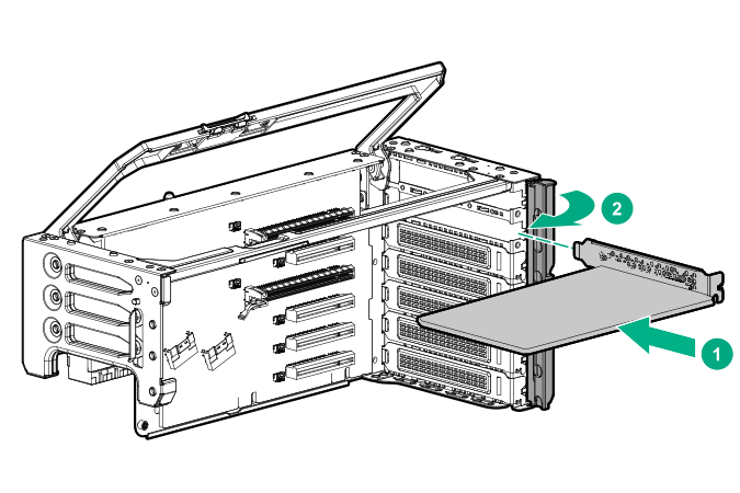
Install the adapter and auxiliary cards into supported slots.
 Two-processor configuration
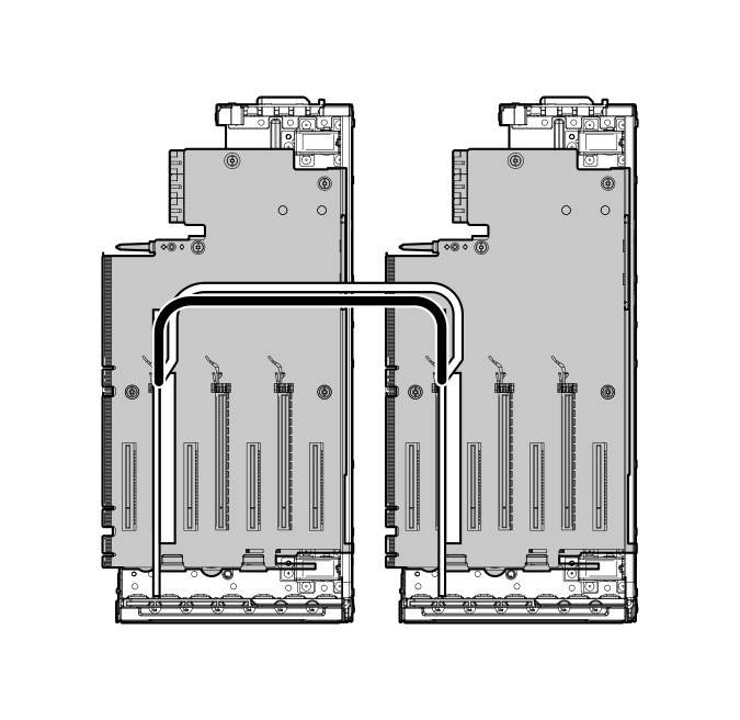 Four-processor configuration