Replacing the system board

To replace the system board assembly:

Procedure

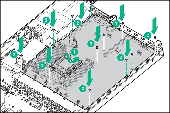
  1. Install the system board assembly.


    Install the system board assembly

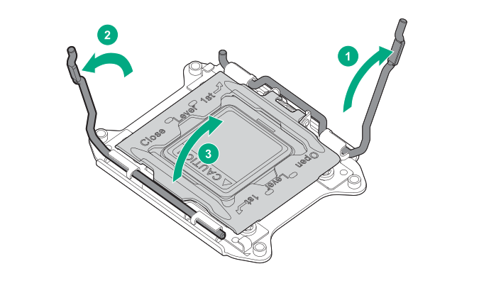
  2. Open each of the processor locking levers in the order indicated, and then open the processor retaining bracket.


    Opening the processor locking levers

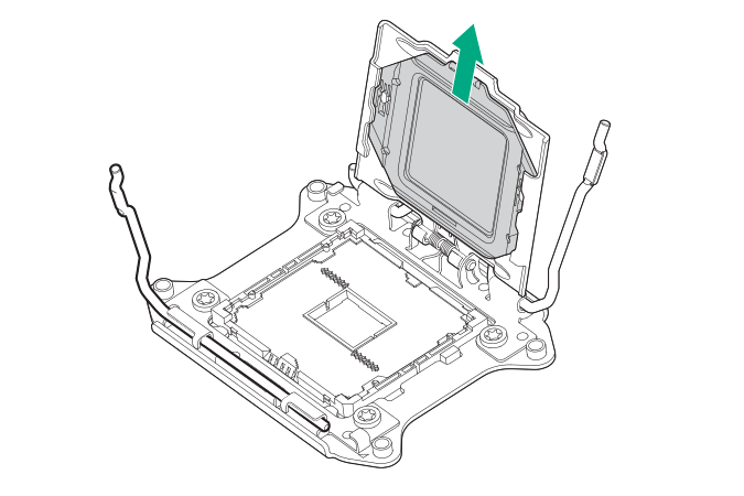
  3. Remove the clear processor socket cover. Retain the processor socket cover for future use.


    Removing the processor socket cover

  4. Install the processor.

    Verify that the processor is fully seated in the processor retaining bracket by visually inspecting the processor installation guides on either side of the processor. THE PINS ON THE SYSTEM BOARD ARE VERY FRAGILE AND EASILY DAMAGED.


    Installing the processor and verifying that it is fully seated

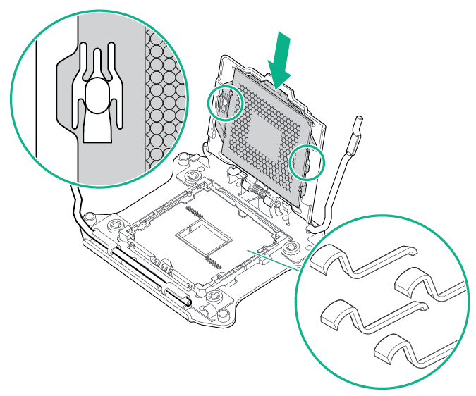
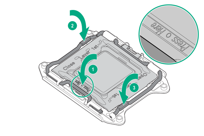
    CAUTION: Do not press down on the processor. Pressing down on the processor might damage the processor socket and the system board. Press only in the area indicated on the processor retaining bracket.
    CAUTION: Close and hold down the processor cover socket while closing the processor locking levers. The levers should close without resistance. Forcing the levers closed can damage the processor and socket, requiring system board replacement.
  5. Close the processor retaining bracket. When the processor is installed properly inside the processor retaining bracket, the processor retaining bracket clears the flange on the front of the socket.
  6. Press and hold the processor retaining bracket in place, and then close each processor locking lever. Press only in the area indicated on the processor retaining bracket.


    Pressing and holding the processor retaining bracket

  7. Install the processor socket cover on the failed system board.
  8. Clean the old thermal grease from the heatsink with the alcohol swab. Allow the alcohol to evaporate before continuing.
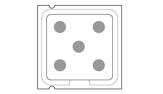
  9. Apply all the grease to the top of the processor in the following pattern to ensure even distribution.


    Grease pattern

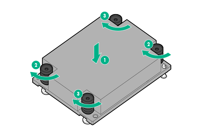
  10. Install the heatsink
    1. Tighten one pair of diagonally opposite screws halfway, and then tighten the other pair of screws.
    2. Finish the installation by completely tightening the screws in the same sequence.


    Installing the heatsink

  11. Install the fans.
  12. Install all components removed from the failed system board.
  13. Connect all cables disconnected from the failed system board.
  14. Install the PCI riser cages.
  15. Install the air baffle.
  16. Install the access panel.
  17. Do one of the following:
    • Slide the server into the rack.
    • Install the server into the rack.
  18. Connect each power cord to the server.
  19. Connect each power cord to the power source.
  20. Press the Power On/Standby button.

    The server exits standby mode and applies full power to the system. The system power LED changes from amber to green.

    IMPORTANT: Install all components with the same configuration that was used on the failed system board.
  21. Re-enter the server serial number and product ID.