Installing an HPE InfiniBand HDR/Ethernet 200 GB 1-port 940QSFP56 x16 adapter and auxiliary card
The server supports installing one adapter in a two-processor configuration. The adapter requires the installation of an auxiliary card.
An HPE InfiniBand HDR/Ethernet 200 GB 1-port 940QSFP56 x16 adapter is installed in slot 1 and auxiliary card is installed in slot 2.
For more information of HPE InfiniBand HDR/Ethernet 100 GB 1-port 940QSFP56 x16 adapter installation, see Expansion board options.
The connector pins are fragile and easily damaged. To avoid damaging the connector pins, do not use excessive force when connecting the cables.
Before you perform this procedure, make sure that you have the following items available:
T-10 Torx screwdriver
T-15 Torx screwdriver
Phillips No. 2 screwdriver
HPE InfiniBand HDR PCIe G3 Auxiliary card with 350 mm cable kit (P06154-B23)
-
Remove the primary riser slot blank.
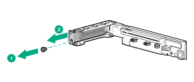
Retain the primary riser slot blank and screw for future use.
-
If installed, remove the full-height bracket from the adapter.
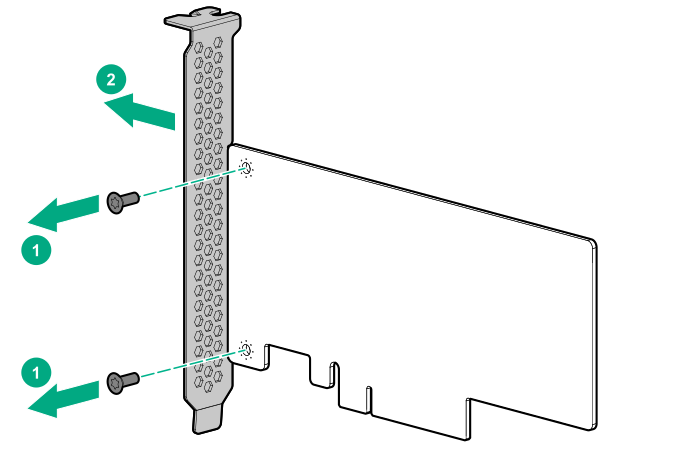
Retain the full-height bracket and screws for future use.
-
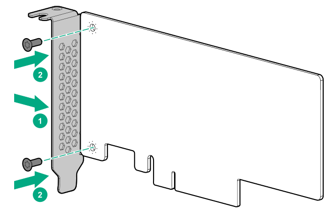
Install the low-profile bracket provided in the kit on the adapter and the auxiliary card.
-
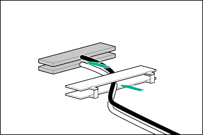
Thread the two cables provided in the kit together using the cable retention clip on either ends of the cables. Ensure that the clip posts are pointing towards the cable ends.
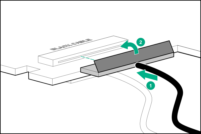
CAUTION:The white and black cables from the auxiliary card connect to the adapter board ports labeled WHITE CABLE and BLACK CABLE, respectively. The cable latch door must be open when connecting the cables. Close the cable latch door after connecting the cable.
-
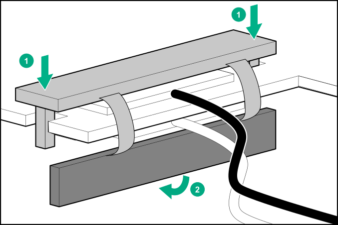
Install the cables on the adapter:
- Close the cable latch door until it clicks into place.
IMPORTANT:The connector is very delicate. To avoid the risk of breaking or bending the connector, push in the connector very gently. Do not touch the connector to avoid oil and dirt transfer to the connection area.
- Close the cable latch door until it clicks into place.
-
Push the down the clip and slide the cable retention clip on the adapter.
-
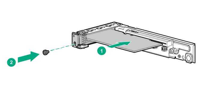
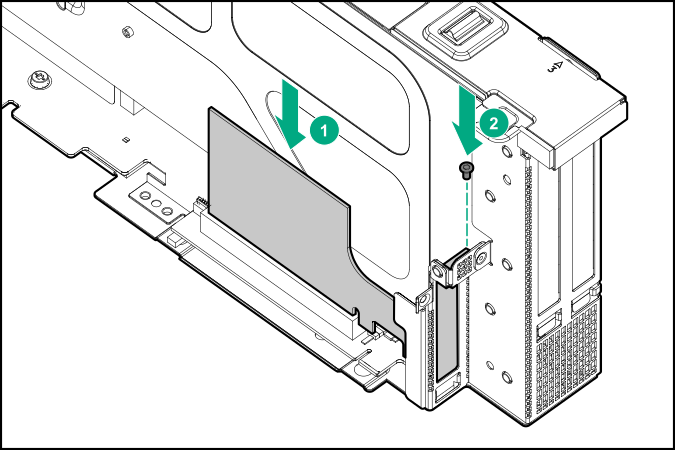
Install the adapter in the primary riser cage.
-
To install the auxiliary card in secondary riser cage, do the following:
- Remove the secondary riser slot 2 blank.
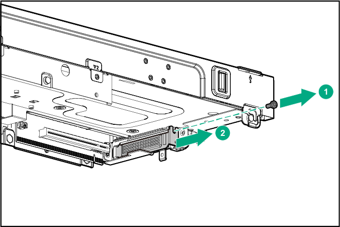
Retain the secondary riser slot blank, retention cover, and screw for future use.
- Lay the secondary riser cage on its side with the riser slots facing up to access the riser slot 2 and install the auxiliary card in slot 2.
- Remove the secondary riser slot 2 blank.
The installation is complete.
For more information on UEFI configurations, see the Hewlett Packard Enterprise website: