Installing the M.2 SSD enablement board
Before you perform this procedure, make sure that you have the following items available:
M.2 SSD enablement option
M.2 SSD
T-10 Torx screwdriver
Phillips No. 1 screwdriver – required only if the M.2 SSD is not preinstalled on the enablement board.
If installing the M.2 SSD enablement board in slot 3, make sure that the processor 2 is installed.
-
If installing the option into slot 2 or slot 3, do the following:
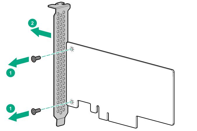
- Remove the full-height bracket from the M.2 SSD enablement board.
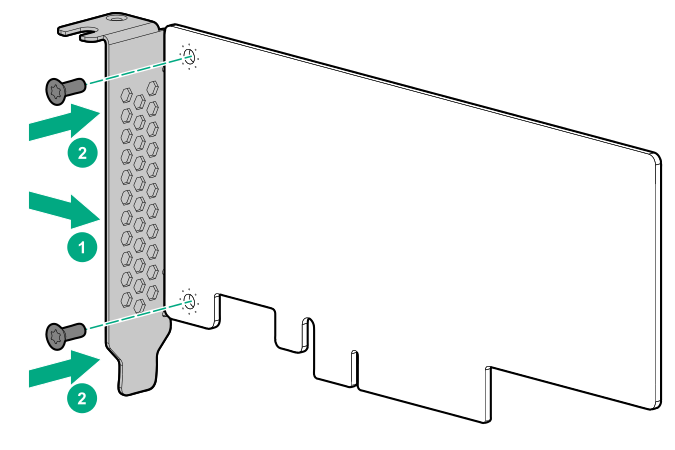
- Install the half-height bracket onto the expansion board.
- Remove the full-height bracket from the M.2 SSD enablement board.
-
If the SSD is not preinstalled on the M.2 SSD enablement board, do the following:
If only one SSD is being installed, install the SSD in slot 1.
- Install the SSD mounting screw.
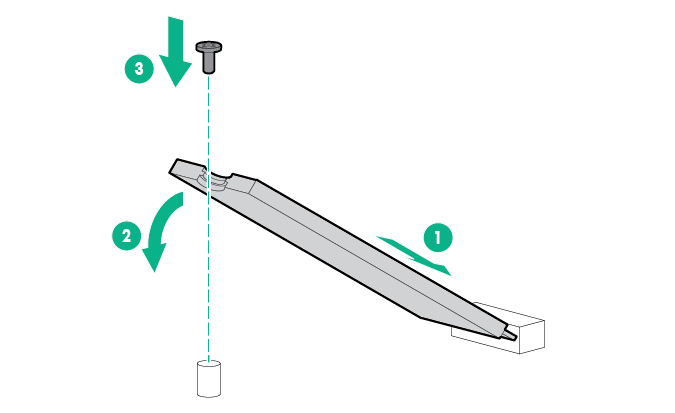
- Install the SSD mounting screw.
-
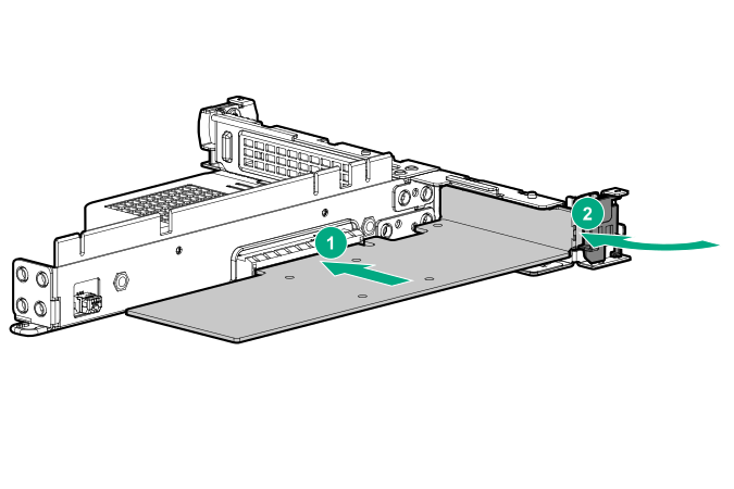
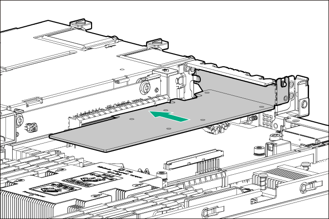
Install the M.2 SSD enablement board with installed SSD modules into the PCI riser cage, and then connect the SATA cables to the enablement board.
- Slot 1

- Slot 2
- Slot 3
If installing the M.2 SSD enablement board in slot 3, a type-a modular storage controller is not supported in the server.
- Slot 1
The installation is complete.
To configure the M.2 SATA SSDs, see the HPE Smart Array SR Gen10 Configuration Guide at the Hewlett Packard Enterprise website.