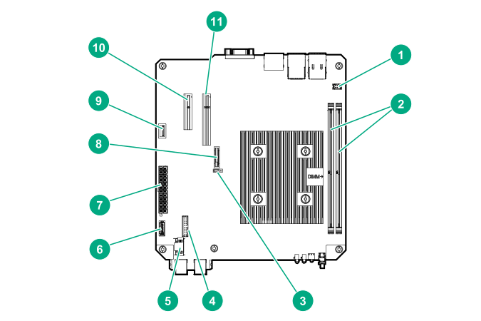
System board components
| Item | Component | Description |
|---|---|---|
1 |
Fan connector |
Connects the fan cable. |
2 |
DIMM slots |
These slots support standard UDIMMs with ECC only. |
3 |
CMOS header |
Use the jumper on this header to clear the CMOS. |
4 |
TPM connector |
This connector supports the TPM 2.0 option for data security solution. |
5 |
LFF/SFF drive SATA port |
Connects the LFF/SFF drive SATA cable.1 |
6 |
Optical drive or SSD SATA port |
Connects the optical drive or SSD SATA cable.1 |
7 |
System board power connector |
Connects the power supply cable. |
8 |
System battery |
This battery provides power to the server real-time clock and BIOS settings. |
9 |
Internal USB 2.0 port |
Connect internal USB devices to this port. |
10 |
Expansion slot 2, PCIe3 ×4 (1) |
For additional hardware capabilities, install a compatible low-profile PCIe expansion board here. This expansion slot supports expansion boards with a physical connector link widths of up to ×16.2 |
11 |
Expansion slot 1, PCIe3 ×8 (8, 4, 1) |
For additional hardware capabilities, install a compatible low-profile PCIe expansion board here. This expansion slot supports expansion boards with a physical connector link widths of up to ×16.2 |
These are SATA 6Gb/s ports.
This expansion slot is open-ended, which enables down-plugging. Down-plugging means a larger-width expansion board can be installed in a smaller-width connector. For this server, the expansion slot supports low-profile expansion boards with a physical connector link widths of up to ×16. The board operates at the highest common negotiable link width specified for the slot.