Removing and replacing an HPE InfiniBand HDR/Ethernet 200 GB 1-port 940QSFP56 x16 adapter and auxiliary card
An HPE InfiniBand HDR/Ethernet 200 GB 1-port 940QSFP56 x16 adapter is installed in slot 1 and auxiliary card is installed in slot 2.
Before you perform this procedure, make sure that you have the following items available:
T-10 Torx screwdriver
T-15 Torx screwdriver
Phillips No. 2 screwdriver
-
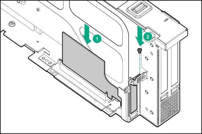
Remove the auxiliary card from slot 2.
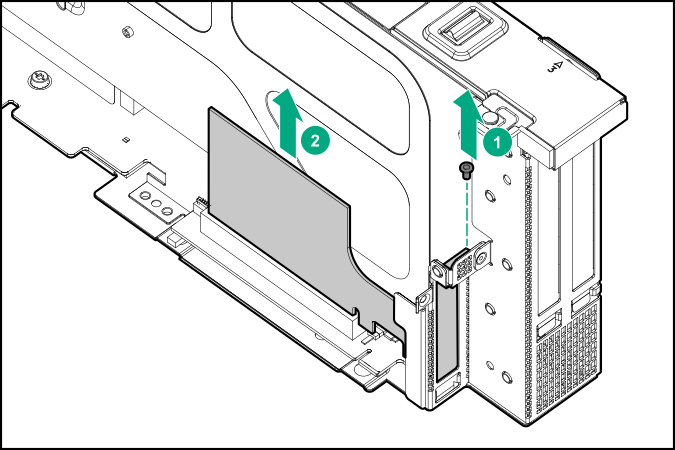
Retain the screw for future use.
-
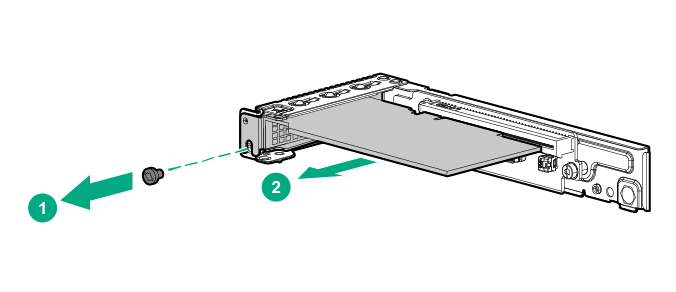
Remove the adapter from slot 1.
To replace the component:
- If installed, remove the full-height bracket from the adapter.
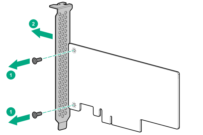
Retain the full-height bracket and screws for future use.
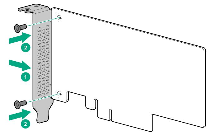
Install the low-profile bracket provided in the kit on the adapter and the auxiliary card.
Thread the two cables provided in the kit together using the cable retention clip on either ends of the cables. Ensure that the clip posts are pointing towards the cable ends.
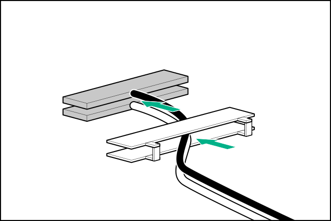
CAUTION:The white and black cables from the auxiliary card connect to the expansion board ports labeled WHITE CABLE and BLACK CABLE, respectively. The cable latch door must be open when connecting the cables.
Install the cables on the adapter:
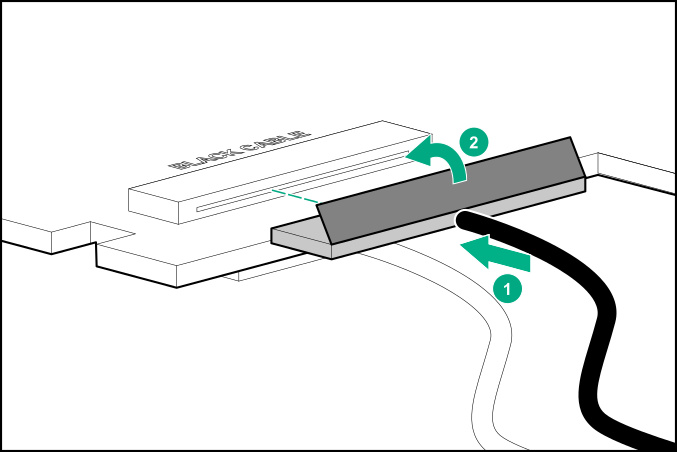
Connect the cable.
Close the cable latch door until it clicks into place.
CAUTION:The connector pins are fragile and easily damaged. To avoid damaging the connector pins, do not use excessive force when connecting the cables.
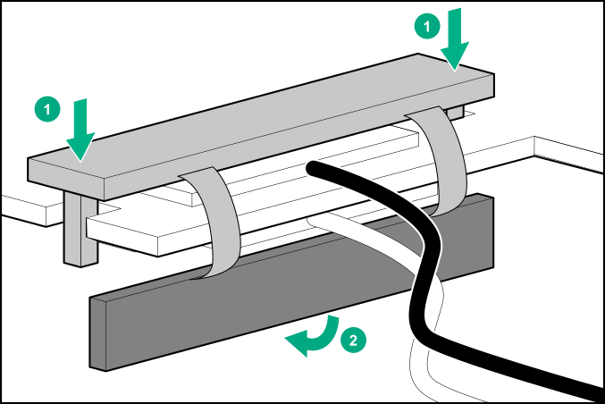
Push the clip down and slide the cable retention clip on the adapter.
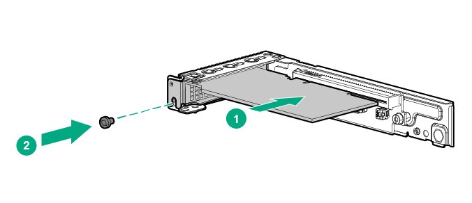
Install the adapter in slot 1.
Thread the cables through the second retention clip.
Install the auxiliary card in slot 2.
Connect all peripheral cables to the server.
Connect all power:
Connect each power cord to the server.
Connect each power cord to the power source.