Installing an SFF drive

To install SFF hard drives and SSDs, use the SFF-to-LFF drive converter option.

In general, SFF drives require as little as half the power and generate less heat than LFF drives.

SSDs have no moving parts. Information is stored in microchips. Traditional hard drives use a mechanical arm with a read/write head to move around and read information from the right location on a rotating storage platter. This lack of rotating media in an SSD:
  • Greatly reduces the drive power consumption in the server.

  • Enable an SSD to tolerate higher operating shock and vibration levels. SSDs are suitable for server workloads with highly random data under a variety of write-workload applications.

Prerequisites

Before you perform this procedure, make sure that you have the following items available:

  • T-10 Torx screwdriver

  • T-15 Torx screwdriver

  • SFF drive converter option kit. This kit includes:

    • Drive converter tray

    • T-10 screws (4)

Procedure
  1. Power down the server.
  2. Disconnect the power cord from the AC source.
  3. Remove the power adapter cord from the power cord clip, and then disconnect the power adapter from the server.
  4. Disconnect all peripheral cables from the server.
  5. If installed, unlock and remove the security padlock and/or the Kensington security lock.

    For more information, see the lock documentation.

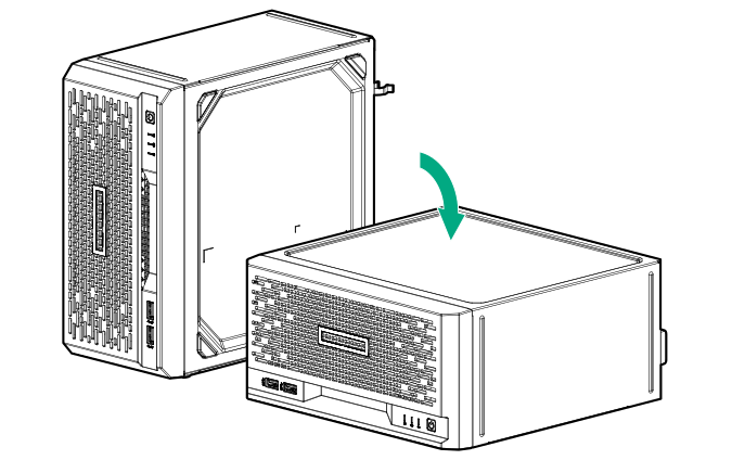
  6. If the server is in a vertical orientation, position the server in a horizontal orientation.

    Positioning the server in a horizontal orientation
  7. Remove the front bezel.
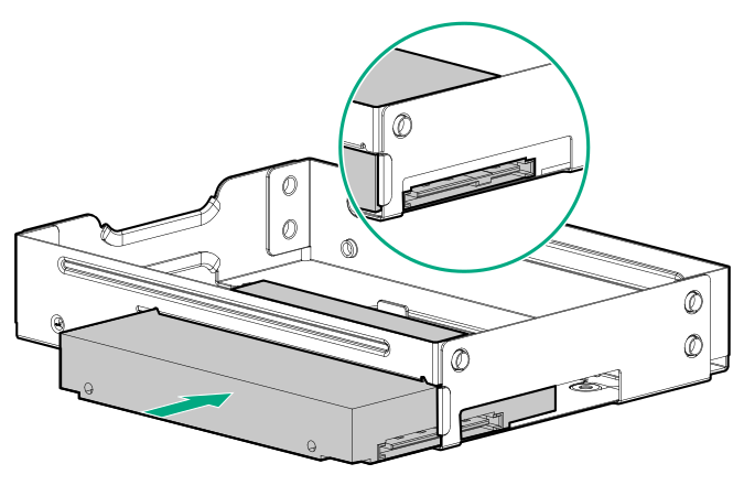
  8. Install the SFF drive in the drive converter tray.

    Installing an SFF drive in the drive converter tray
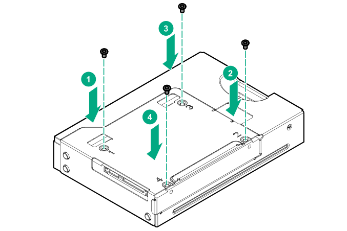
  9. To install the screws included in the converter kit, follow the callout sequence in the following illustration.

    Installing the drive screws on the bottom of the drive converter tray
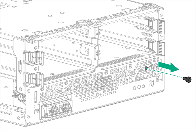
  10. Remove three drive screws from the front panel.

    Removing the drive screws from the front panel
  11. Install the three screws removed from the front panel on the left and right sides of the drive converter tray.

    Installing the SFF drive screws
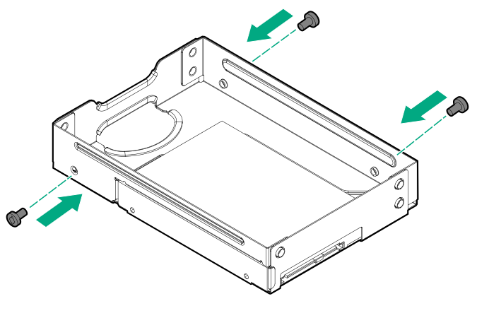
  12. Slide the drive converter tray into the bay until it clicks into place.

    Installing the drive converter tray
  13. Install the front bezel.
  14. If removed, install the security padlock and/or the Kensington security lock.

    For more information, see the lock documentation.

  15. Connect all peripheral cables to the server.
  16. Connect the power adapter to the server, and then secure the power adapter cord in the power cord clip.
  17. Connect the power cord to the AC source.
  18. Power up the server.
  19. Determine the status of the server drives.

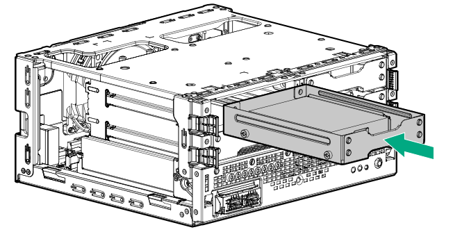
The installation is complete.

To configure arrays, see the HPE Smart Array SR Gen10 Configuration Guide at the Hewlett Packard Enterprise website.