Be sure to note the DIMM slot locations in which each DIMM is installed. These components must be installed in the same locations on the new system board.
Be sure to note the DIMM slot locations in which each
HPE Persistent Memory module is installed. These components must be installed in the same locations on the new system board.
Disconnect all cables connected to the system board.
Observe the following cautions.
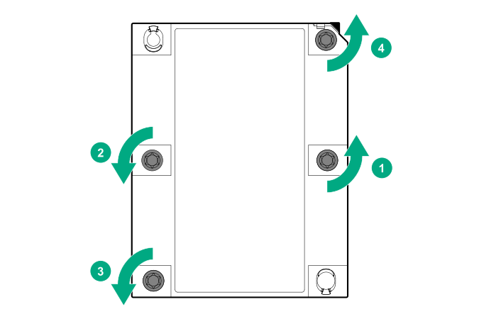
CAUTION: Be sure to loosen each heatsink nut in the order indicated. Otherwise, damage might occur to the heatsink or processor.
CAUTION: Install the processor heatsink assembly as soon as possible after removing it. Do not leave the processor socket unpopulated for extended periods of time.
Remove the processor-heatsink assembly:
Allow the heatsink to cool.
Using a T-30 Torx screwdriver, loosen the heatsink nuts.
Lift the processor-heatsink assembly up and away from the system board.
Turn the processor-heatsink assembly over on a work surface with the processor facing up.
Install the dust cover on each processor socket on the failed system board.
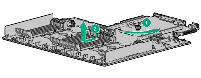
Loosen the system board thumbscrews.
Remove the system board, using the handle to lift it out of the chassis.
Replacing the system board
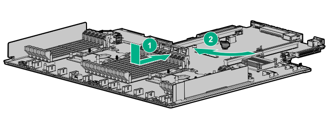
Install the spare system board.
Install the processor-heatsink assembly:
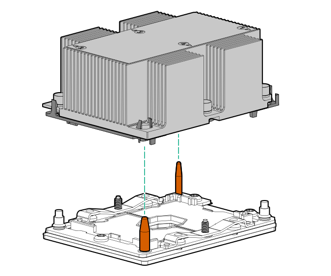
Locate the Pin 1 indicator on the processor carrier and the socket.
Align the processor-heatsink assembly with the heatsink alignment pins and gently lower it down until it sits evenly on the socket.
The heatsink alignment pins are keyed. The processor-heatsink assembly will only install one way.
Your heatsink might look different than the one shown.
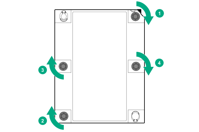
Using a T-30 Torx screwdriver, fully tighten each heatsink nut until it no longer turns.
CAUTION: Be sure to tighten each heatsink nut fully in the order indicated. Otherwise, boot failure or intermittent shutdowns might occur.
IMPORTANT: Install all components with the same configuration that was used on the failed system board.
Install all components removed from the failed system board.
Be sure to install the DIMMs and
HPE Persistent Memory modules in the same DIMM slots as the failed system board.
Install the access panel.
Install the power supplies.
Power up the
server.
Ensure all firmware, including option cards and embedded devices, is updated to the same versions to ensure that the latest drivers are being used.
Re-enter any Secure Boot Keys that were previously added in the Secure Boot configuration.
If
HPE Persistent Memory modules are encrypted with local key management, either manually enter the
HPE Persistent Memory module passwords in the System Utilities or import the password file from the USB key.
If
HPE Persistent Memory modules are encrypted with remote key management, enroll the
server iLO in the key management server to provide access to the data on the
HPE Persistent Memory modules.
 IMPORTANT: Install all components with the same configuration that was used on the failed system board.