Installing the HPE 12G SAS Expander Card
Hewlett Packard Enterprise recommends installing the SAS expander card in slot 2 of the primary PCIe riser cage.
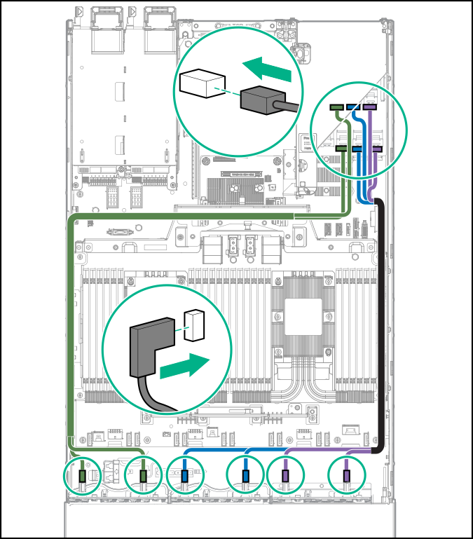
To ensure that cables are connected correctly, observe the labels on the cable and component connectors.
Be sure that you have the latest firmware for the controllers, HBAs, and the HPE 12G SAS Expander. To download the latest firmware, see the Hewlett Packard Enterprise website (http://www.hpe.com/support/hpesc).
| Cable | Description | Connection to SAS expander | Connection to controller |
|---|---|---|---|
| 874067-001 | Mini-SAS cable, Smart Array Controller to expander | Port 1, Port 2 | Riser 1, Smart Array controller |
| Cable | Description | Connection to SAS expander | Connection to controller |
|---|---|---|---|
| 880028-001 | 2x4 SAS cable, expander to H240 | Port 1, Port 2 | Riser 2 |
| 880029-001 | 2x4 SAS cable, expander to Smart Array controller | Port 1, Port 2 | Riser 3 |
| Cable | Description | Connection to SAS expander | Connection to drive box |
|---|---|---|---|
| 874066-001 | Mini-SAS cable, expander to 2SFF | Port 3, Port 4 | Box 1 |
| 874064-001 | Mini-SAS cable, expander to 2SFF | Port 5, Port 6 | Box 2 |
| 874065-001 | Mini-SAS cable, expander to 2SFF | Port 7, Port 8 | Box 3 |
| 874063-001 | Mini-SAS cable, expander to 2SFF | Port 3 | Box 1 |
Controller backup power cables
| Cable | Description |
|---|---|
| 878645-001 | Controller backup power cable (short) |
| 878646-001 | Controller backup power cable (long) |
The 12G SAS Expander Card supports up to 24 SFF drives, depending on which options are also installed in the server.
The following components must be installed:
Storage controller
Drive cages
24SFF drive configuration—Bay 1, bay 2, and bay 3 installed with 8SFF front drive cages
18SFF drive configuration—Bay 1 Universal Media Bay installed with 2SFF drive cage option, and bay 2 and bay 3 installed with 8SFF front drive cages.
16SFF drive configuration—Bay 2 and bay 3 installed with 8SFF drive cages
-
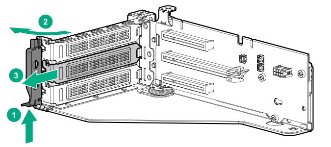
Remove the expansion slot blank from slot 2.
-
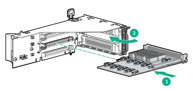
Install the SAS expander card.
-
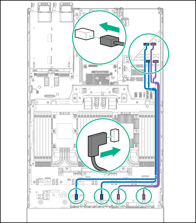
Using the labels on the cables to determine the correct connections, connect the cables from the SAS expander card to the controller.
Flexible Smart Array Controller with two x4 connectors (Group B SAS cables)
PCI slot-based Smart Array controller with x8 connector (Group A SAS cables)

-
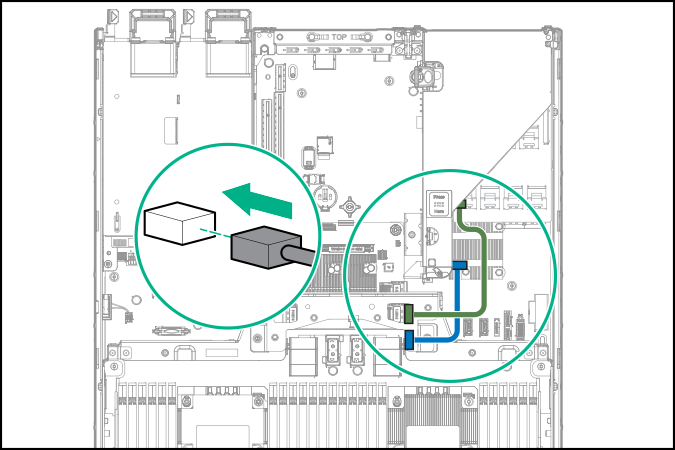
Connect the cables to the drive cage backplanes:
24 SFF backplanes (Group C SAS cables)
18 SFF backplanes (Group C SAS cables)

16 SFF backplanes (Group C SAS cables)