Install the Smart Array P440 Controller Mini-SAS Y-cable for a rear drive cage option
- Power down the server.
-
Remove all power:
- Disconnect each power cord from the power source.
- Disconnect each power cord from the server.
- Remove the server from the rack.
- Remove the access panel.
- Remove the air baffle.
-
If you are installing the P440 controller for the four-bay LFF hot-plug rear drive cage, do one of the following:
- Disconnect the Mini-SAS cable connected to the front drive cage 2 backplane from the rear drive backplane.
- Disconnect the Mini-SAS cable from the rear drive backplane and from the system board.
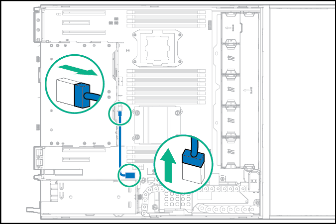
- Disconnect the Mini-SAS cable connected to the front drive cage 2 backplane from the rear drive backplane.
-
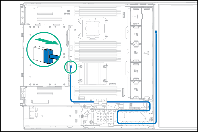
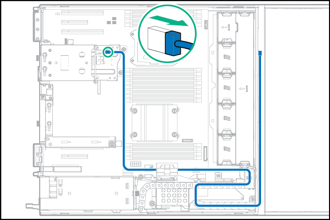
If you are installing the P440 controller for a two-bay SFF hot-plug rear drive cage that is connected to the front drive cage 2 backplane, disconnect the preinstalled Mini-SAS x4 cable from the two-bay SFF rear drive backplane.
-
If you are installing the P440 controller for a two-bay SFF hot-plug rear drive cage that is connected to the system board, disconnect the multiconnector drive signal cable:
- Open the cable management holder.
-
Disconnect the multiconnector drive signal cable from the rear drive backplane and from the system board.
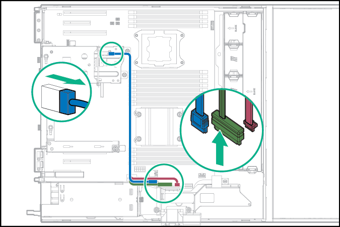
- Close the cable management holder.
-
Remove the air scoop from the storage controller.
- If you intend to use an FBWC module, install the module on the storage controller.
-
For the four-bay LFF rear drive cage – Install the P440 controller in the low-profile PCIe expansion slots 1, 2, 5, 6 or 7:
For the two-bay SFF rear drive cage – Install the P440 controller in the low-profile PCIe expansion slots 1, 5, 6 or 7:
-
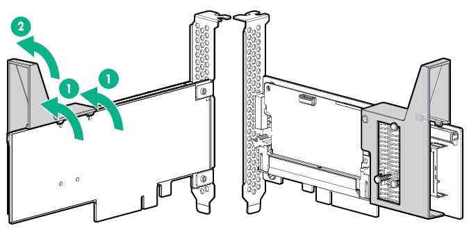
Remove the full-height bracket from the storage controller and attach the low-profile bracket.
For more information, see the documentation that ships with the option.
-
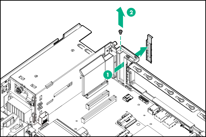
Remove the onboard PCI expansion slot cover.
-
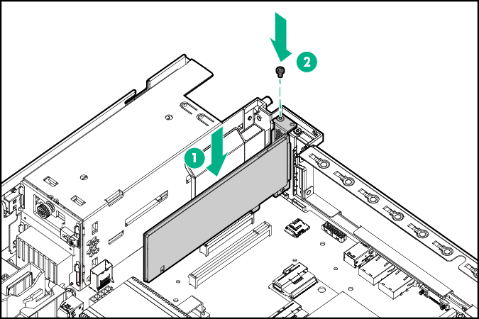
Install the storage controller.
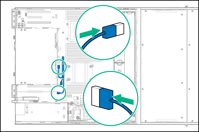
- Connect the Mini-SAS Y-cable to the rear drive backplane and the storage controller.
-
Depending on the drive configuration type and the location of the controller board, secure the Mini-SAS Y-cable in the system board clips or position it on top of the air baffle.
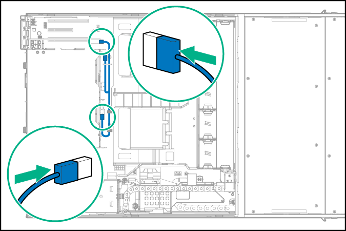
- Four-bay LFF rear drive cage – P440 controller Mini-SAS Y-cable connection from the PCIe expansion slot 1 or 2
- Four-bay LFF rear drive cage – P440 controller Mini-SAS Y-cable connection from the PCIe expansion slot 5, 6 or 7
- Two-bay SFF rear drive cage – P440 controller Mini-SAS Y-cable connection from the PCIe expansion slot 1
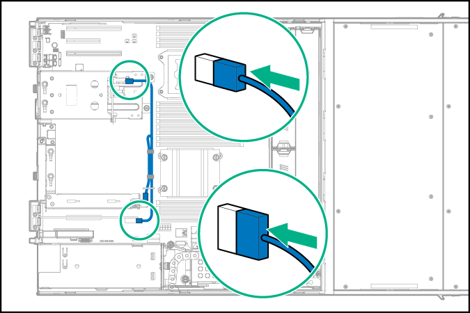
- Two-bay SFF rear drive cage – P440 controller Mini-SAS Y-cable connection from the PCIe expansion slot 5, 6 or 7
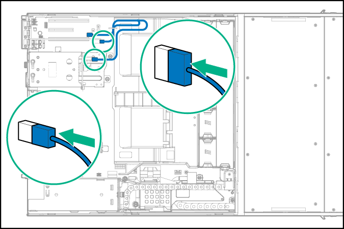
- Four-bay LFF rear drive cage – P440 controller Mini-SAS Y-cable connection from the PCIe expansion slot 1 or 2
-
Remove the full-height bracket from the storage controller and attach the low-profile bracket.
-
For the two-bay SFF rear drive cage only – Install the P440 controller in the riser board slot 3 or 4:
- Remove the PCI riser cage.
-
Remove the riser slot cover.
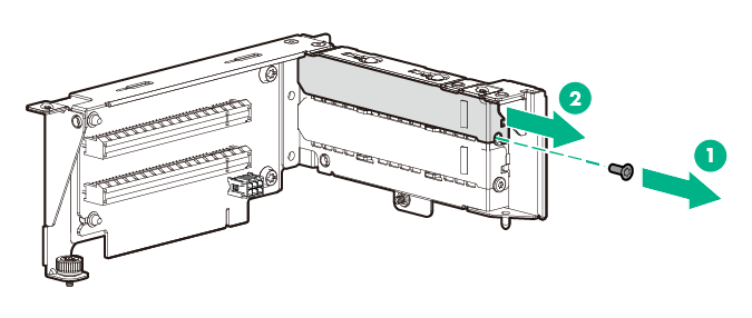
-
Install the storage controller.
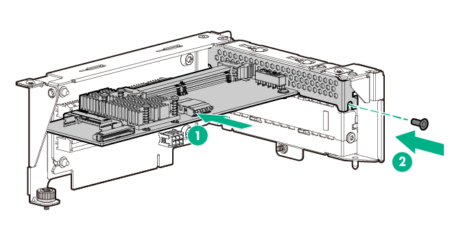
- Install the PCI riser cage.
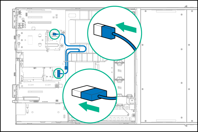
- Connect the Mini-SAS Y-cable to the rear drive backplane and the storage controller.
-
Position the Mini-SAS Y-cable on top of the air baffle.
- Install the access panel.
- Install the server into the rack.
- Power up the server.