Install the processor option
- Power down the server.
-
Remove all power:
- Disconnect each power cord from the power source.
- Disconnect each power cord from the server.
- Remove the server from the rack.
- Remove the access panel.
- Remove the air baffle.
-
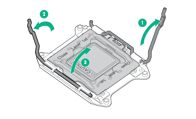
Open each of the processor locking levers in the order indicated in the following illustration, and then open the processor retaining bracket.
-
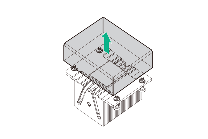
Remove the clear processor socket cover. Retain the processor socket cover for future use.
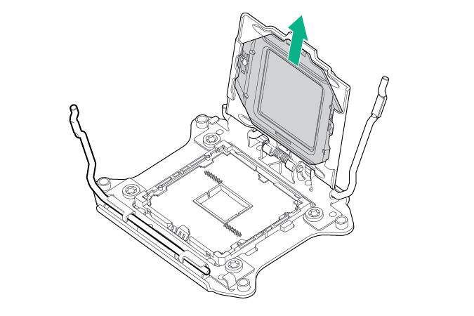 CAUTION: THE PINS ON THE SYSTEM BOARD ARE VERY FRAGILE AND EASILY DAMAGED. To avoid damage to the system board, do not touch the processor or the processor socket contacts.
 -
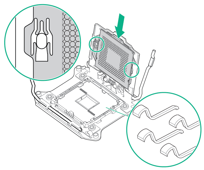
Install the processor. Verify that the processor is fully seated in the processor retaining bracket by visually inspecting the processor installation guides on either side of the processor. THE PINS ON THE SYSTEM BOARD ARE VERY FRAGILE AND EASILY DAMAGED.
-
Close the processor retaining bracket. When the processor is installed properly inside the processor retaining bracket, the processor retaining bracket clears the flange on the front of the socket.
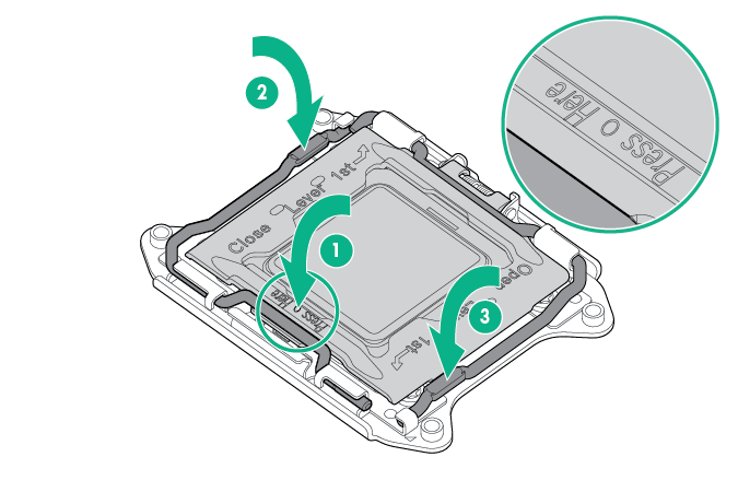
CAUTION: Do not press down on the processor. Pressing down on the processor might damage the processor socket and the system board. Press only in the area indicated on the processor retaining bracket.
-
Press and hold the processor retaining bracket in place, and then close each processor locking lever. Press only in the area indicated on the processor retaining bracket.
-
Remove the thermal interface protective cover from the heatsink.
-
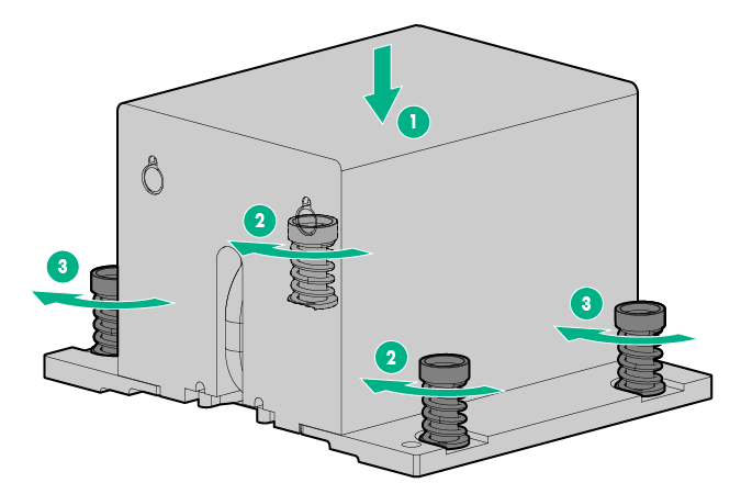
Install the heatsink:
- Position the heatsink on the processor backplate.
- Tighten one pair of diagonally opposite screws halfway, and then tighten the other pair of screws.
-
Finish the installation by completely tightening the screws in the same sequence.
- Install the air baffle.
-
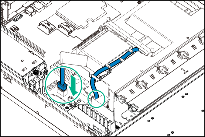
If disconnected, connect the Smart Storage Battery cable.
-
If the
server is being upgraded from a single processor, nonredundant fan configuration to a dual-processor, nonredundant fan configuration, install the fan included in this processor option kit:
-
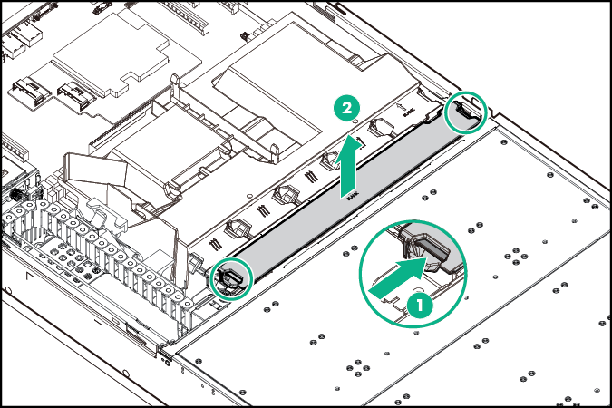
Remove the fan blank from fan bay 5.
-
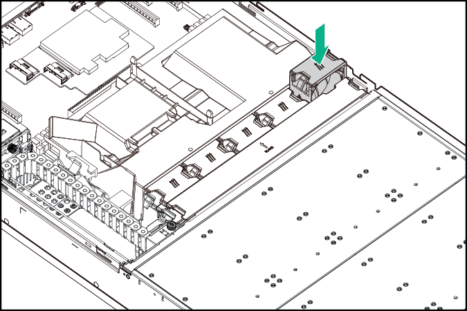
Install the fan in fan bay 5.
-
Remove the fan blank from fan bay 5.
-
To enable fan redundancy in a dual-processor configuration, all 10 fan bays should be populated. Obtain a Redundant Fan Option Kit (PN 806562-B21) and install five more fans in fan bays 6–10:
-
Remove the fan cage cover.
-
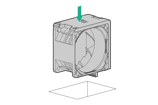
Install the fans in fan bays 6–10.
-
Remove the fan cage cover.
-
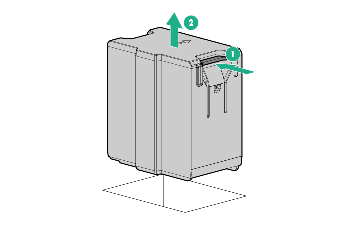
The PCIe expansion slots 5–7 are associated with processor 2. To enable expansion board installation in these now active slots, remove the slot cover air blocker.
-
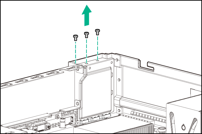
Remove the air blocker screws.
-
Insert a pen or a small screwdriver into one of the slot cover hole to push the air blocker down, and then remove the air blocker from the
chassis.
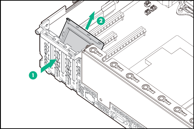
Retain the air blocker for future use.
-
Remove the air blocker screws.
- Install the access panel.
- Install the server into the rack.
- Power up the server.