Installing the storage controller and FBWC module options
This section only covers the installation of a storage controller board option for the front drive cage 2. The front drive cage 1 is always connected to port 2 of the onboard Flexible Smart Array P840ar Controller.
In this server, Smart HBA option installation is only for external connectivity to tape drives, shared storage, and external JBODs. See the option documentation for external storage cabling information.
- Power down the server.
-
Remove all power:
- Disconnect each power cord from the power source.
- Disconnect each power cord from the server.
- Remove the server from the rack.
- Remove the access panel.
- Remove the air baffle.
-
If installed, remove the air scoop from the storage controller/HBA.
For more information, see the documentation that ships with the option.
-
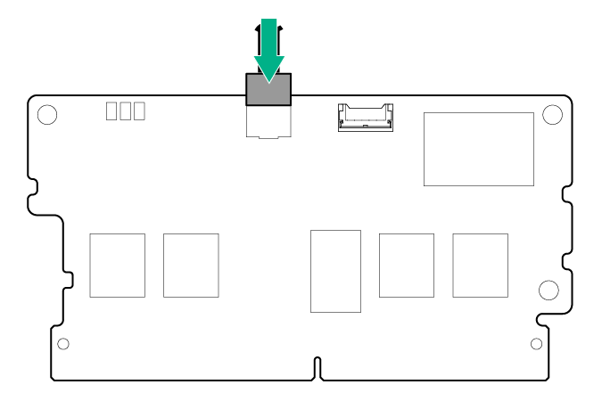
If you intend to use an FBWC module, install the module on the storage controller. Depending on the controller model, the cable connector on the cache module might be facing up or down when the module is installed on the controller board.
-
Connect the cache module backup power cable to the module.
-
Install the cache module on the storage controller.
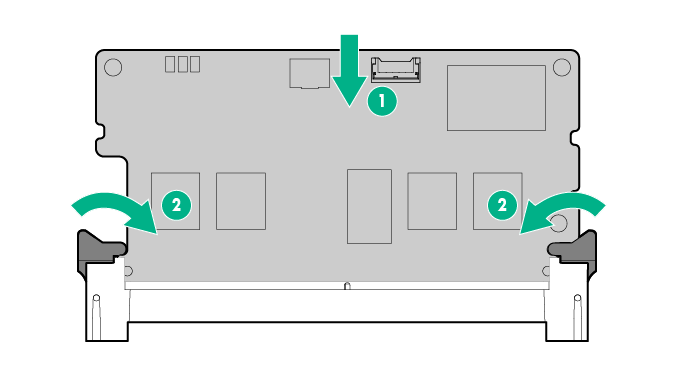
-
Connect the cache module backup power cable to the module.
- If installed, remove the rear drive cage.
- If installed, remove the six-bay SFF rear drive cage.
- If an expansion board is installed on the PCI riser cage, remove the PCI riser cage.
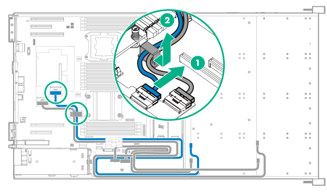
-
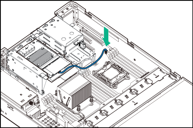
Disconnect the Mini-SAS Y-cable from the Flexible Smart Array P840ar Controller port 1, and then release it from the cable clip.
- Install the storage controller.
- Connect all necessary internal cables to the storage controller. For internal drive cabling information, see "Storage cabling" section in the server user guide.
-
If a cache module is installed on a storage controller located in the onboard PCIe expansion slots 1 or 2, do the following:
- Open the cable management holder.
-
Connect the cache module backup power cable to the system board.
- Close the cable management holder.
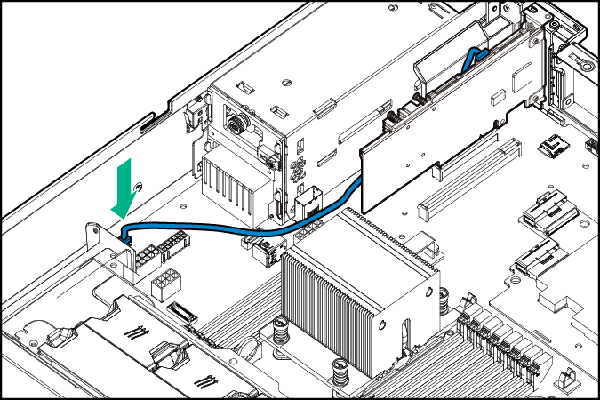
-
If a cache module is installed on a storage controller located in the PCI riser cage, connect the cache module backup power cable to any of the storage backup power connectors located in front of the onboard PCIe expansion slot 7.
- If you are planning to install the Smart Storage Battery Pack, install it now.
- Install the air baffle.
- Install the access panel.
- Install the server into the rack.
- Power up the server.
For more information about the integrated storage controller and its features, select the relevant user documentation on the Hewlett Packard Enterprise website.
To configure arrays, see the HPE Smart Storage Administrator User Guide on the Hewlett Packard Enterprise website.