Replacing the system board
Before you perform this procedure, make sure that you have the following items available:
- T-15 screwdriver (for system board screws)
- T-20 screwdriver (processor and heatsink screws)
- Thermal grease (Spare part number: 777298-001)
-
Install the spare system board.
- Place the spare system board in the chassis, holding the handle.

- Place the spare system board in the chassis, holding the handle.
-
Install the processor:
- Hold the lift tabs near the front end of the rail frame, and then pivot the rail frame to the closed position.
A click sound indicates that the rail frame is properly engaged.
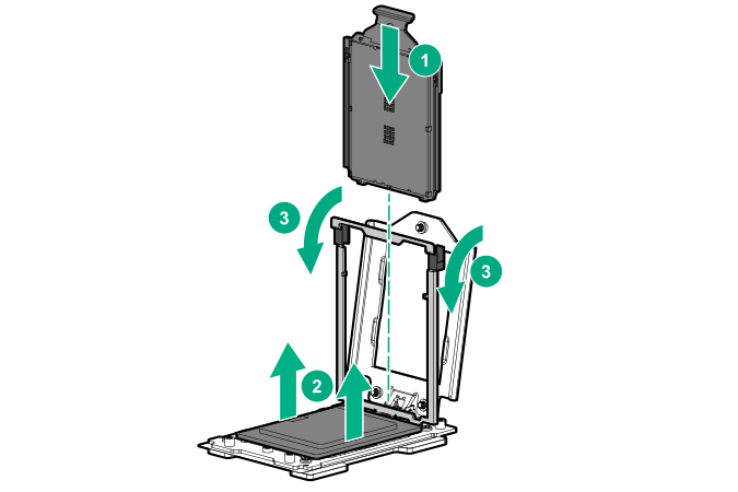
- Hold the lift tabs near the front end of the rail frame, and then pivot the rail frame to the closed position.
-
Apply new thermal grease to the processor in the pattern shown in the following image. Use the full contents of the thermal grease syringe.

-
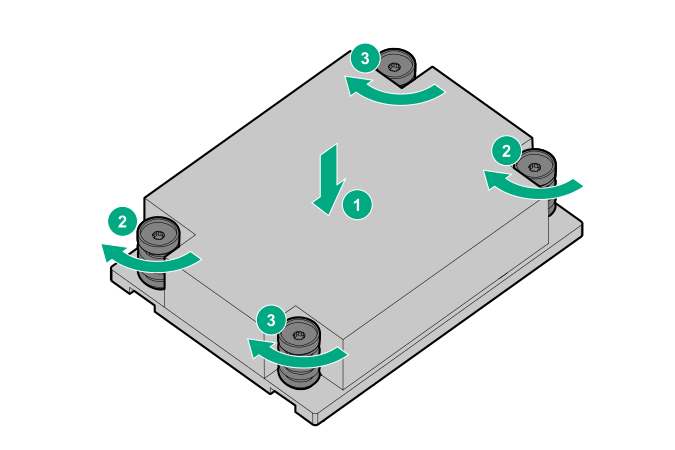
Install the heatsink:
CAUTION:
To prevent mechanical damage or depositing oil on your hands or other contaminant to the heatsink contact surface, hold the heatsink only by the edge of its base plate. Do not touch the heatsink fins.
CAUTION:To prevent thermal failure or component damage, do not move the heatsink once the bottom of its base plate touches the top of the processor. Excessive heatsink movement can cause the thermal grease to smear and become uneven. Voids in the compound can adversely impact the transfer of heat away from the processor.
CAUTION:Heatsink screws must be tightened and loosened in alternating sequence. Do not overtighten the screws as this might damage the system board or the processor socket.