Installing an M.2 SSD enablement option

The DL180 Gen10 M.2 cable kit is required to meet the system thermal requirement. Do not use the M.2 cable that ships with the M.2 SSD enablement option.

Prerequisites

Before you perform this procedure, make sure that you have the following items available:

  • M.2 SSD enablement option

  • M.2 SSD

  • DL180 Gen10 M.2 cable kit (PN 875135-B21)

  • T-10 Torx screwdriver

  • Phillips No. 1 screwdriver – required only if the M.2 SSD is not preinstalled on the enablement board.

Procedure
  1. If installed, remove the front bezel.
  2. Power down the server.
  3. Remove all power:
    1. Disconnect each power cord from the power source.
    2. Disconnect each power cord from the server.
  4. Disconnect all peripheral cables from the server.
  5. Do one of the following:
  6. Remove the access panel.
  7. Remove the riser cage.
  8. Remove the expansion slot blank.
  9. If the SSD is not preinstalled on the M.2 SSD enablement board, do the following:

    If only one SSD is being installed, install the SSD in slot 1.

    1. Insert the SSD into the M.2 slot at a 45° angle.
    2. Carefully press the SSD down to the horizontal position.
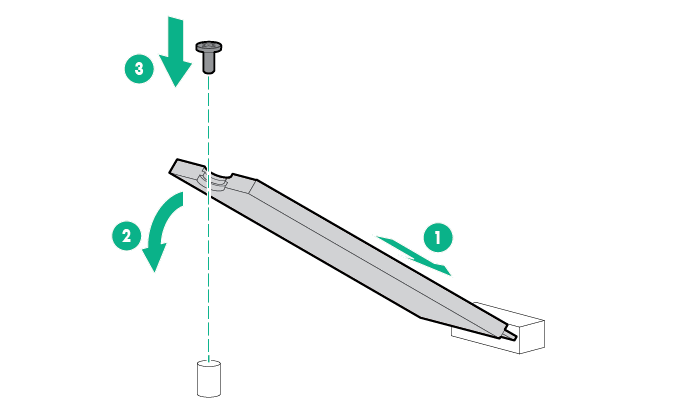
    3. Install the SSD mounting screw.

      Installing an M.2 SSD
    4. If you are installing a second SSD, repeat steps a–c.
  10. Connect the SATA cable to enablement board.
  11. Install the M.2 enablement board.
  12. Install the riser cage.
  13. Connect the SATA cable to system board according to the label indication.
  14. Install the access panel.
  15. Install the server into the rack.
  16. Connect all peripheral cables to the server.
  17. Connect each power cord to the server.
  18. Connect each power cord to the power source.
  19. Power up the server.
  20. If removed, install the front bezel.

The installation is complete.

To configure the M.2 SATA SSDs, see the HPE Smart Array SR Gen10 Configuration Guide at the Hewlett Packard Enterprise website.