Installing an expansion board or type -p controller
CAUTION: To prevent damage to electrical components, take the appropriate anti-static precautions before beginning any installation, removal, or replacement procedure. Improper grounding can cause electrostatic discharge.
CAUTION:
For proper cooling, do not operate the system without the access panel, baffles, expansion slot covers, or blanks installed.
The steps shown apply to both installing an expansion board and installing a type -p controller.
Procedure
-
To install a low-profile, standup expansion board or type -p controller on the system board, do the following:
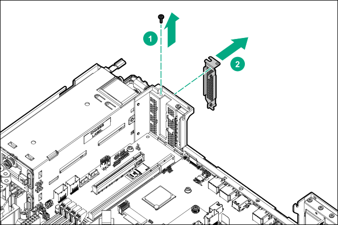
- Remove the onboard PCIe expansion slot cover.
- If installing a type -p controller, connect the controller backup power cable to the system board (Cabling).
IMPORTANT:To enable SmartCache or CacheCade in a P-class type-p Smart Array controller, you must:
Connect the controller backup power cable to the controller backup power connector on the system or riser board.
Connect the energy pack cable to the energy pack connector on the system board.
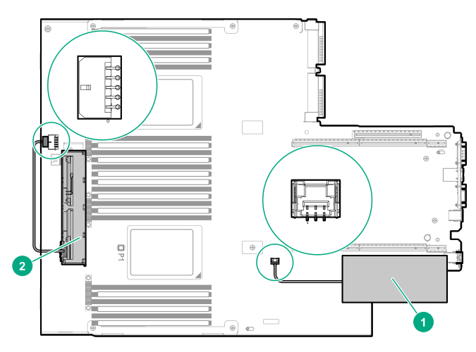
Item Description1 1 Type-p Smart Array controller connected to the controller backup power connector 2 Energy pack connected to the energy pack connector 1Your server might appear different.
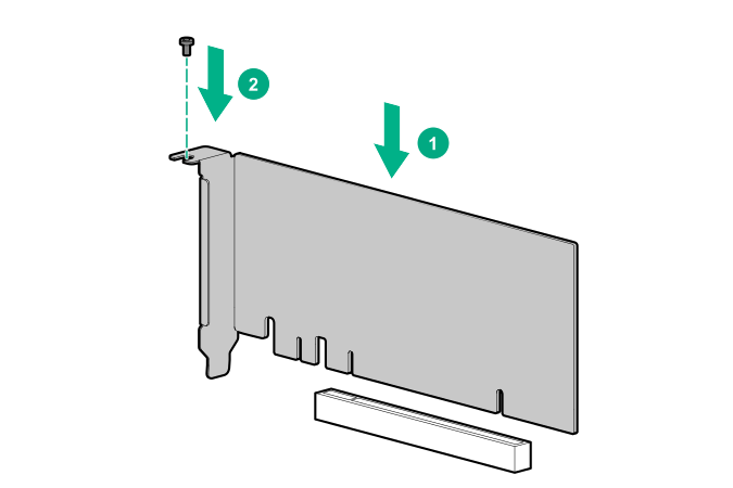
- Install the expansion board or controller. Verify that it is firmly seated in the slot.
- Remove the onboard PCIe expansion slot cover.
-
To install a full-height, half-length PCIe x16 expansion board, the two-slot PCIe riser cage option is required. To install an expansion board or type -p controller in this riser cage, do the following:
- Remove the PCIe riser cage (Remove the PCIe riser cage).
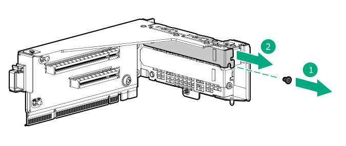
- Remove the riser slot cover.
- If installing an expansion board, verify that any switches or jumpers on the expansion board are set properly. For more information, see the documentation that ships with the option.
- Connect the cables to the expansion board or type -p controller (Cabling).
- Install the expansion board or controller. Verify that it is firmly seated in the slot.
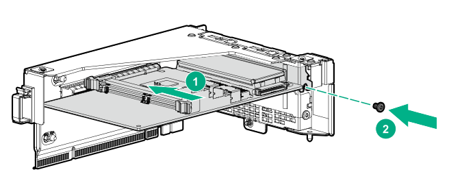
- Install the PCIe riser cage (Installing the two-slot PCIe riser cage).