Installing a SAS LTO tape drive

The half‑height media bay 1 supports the installation of a SAS LTO tape drive option.

Prerequisites
Before you perform this procedure:
  • Make sure that a Smart Array controller board option is installed.

  • In a server that has the maximum number of drives installed in box 2 and box 3, and the RDX drive is present in the half-height media bay 2, make sure that the fan cage is installed.

  • Make sure that you have the following items available:

    • Fan blank

    • LTO tape drive SAS-power Y-cable

    • LTO/RDX power extension Y-cable

    • LTO tape drive option – The SAS and/or power cables that ship with the drive option will not be used in this server.

    • T-15 Torx screwdriver

Procedure
  1. Remove the front bezel.
  2. Power down the server.
  3. Remove all power:
    1. Disconnect each power cord from the power source.
    2. Disconnect each power cord from the server.
  4. Disconnect all peripheral cables from the server.
  5. Do one of the following:
  6. Remove the access panel.
  7. Remove the air baffle.
  8. If installed, remove the fan cage.
  9. Remove the blank from the half-height media bay 1.
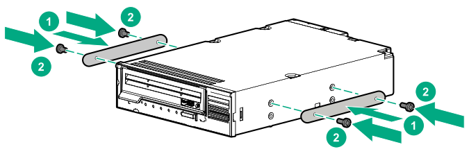
  10. Install the metal shims on the LTO tape drive.

    The shims and the T-15 Torx screws are included in the LTO tape drive option kit.

    If you are installing an LTO tape drive that does not include its own mounting screws, use the preinstalled media drive spare screws.


    Installing the metal shims on the LTO tape drive
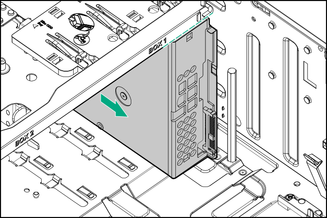
  11. Slide the LTO tape drive into the half‑height media bay 1 until the rear edge of the drive is aligned with the rear edge of the drive box.

    Sliding the LTO tape drive into the half-height media bay 1
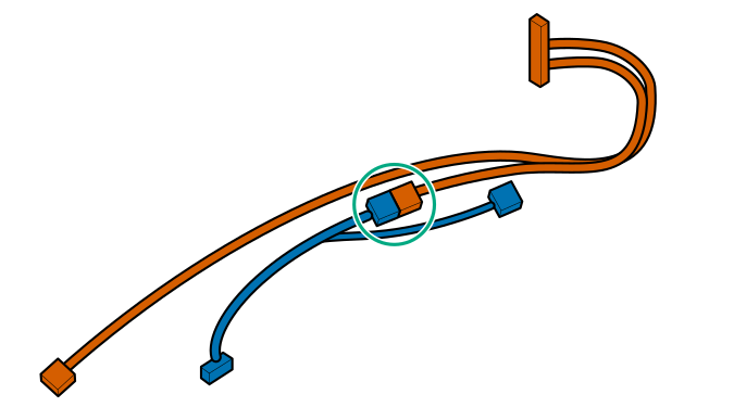
  12. Connect the LTO/RDX power extension Y-cable to the LTO tape drive SAS-power Y-cable.

    Connecting the LTO/RDX power extension Y-cable to the LTO tape drive SAS-power Y-cable
  13. Observe the guidelines for managing cables.
  14. Connect the LTO tape drive cables:
    1. Connect the common end of the SAS-power Y-cable to the LTO tape drive.
    2. Connect the common end of the power extension Y-cable to the drive box 1 power connector.
    3. Connect the SAS end of the SAS-power Y-cable to the Smart Array controller board.

    To view the cable routing, see SAS LTO tape drive cabling.

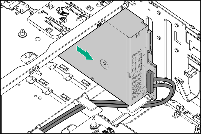
  15. Slide the LTO tape drive fully into the half‑height media bay 1 until it clicks into place.

    Installing the LTO tape drive into the half‑height media bay 1
    CAUTION: To prevent improper cooling and thermal damage, do not operate the server unless all bays are populated with either a component or a blank.
  16. If the fan cage was removed, do the following:
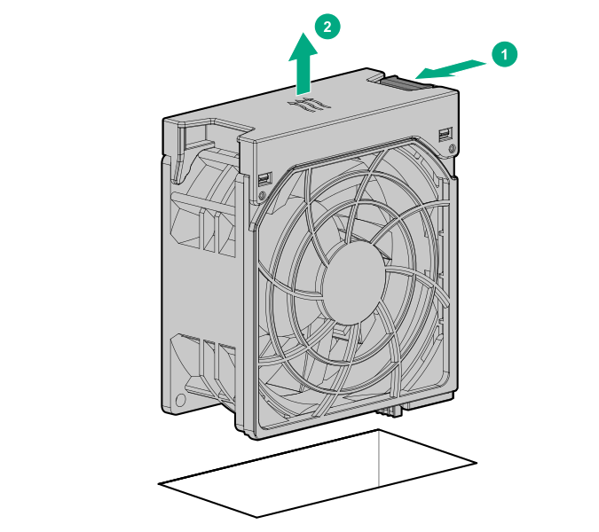
    1. While pressing the release latch, pull up the fan 1 out of the bay.

      Removing a fan
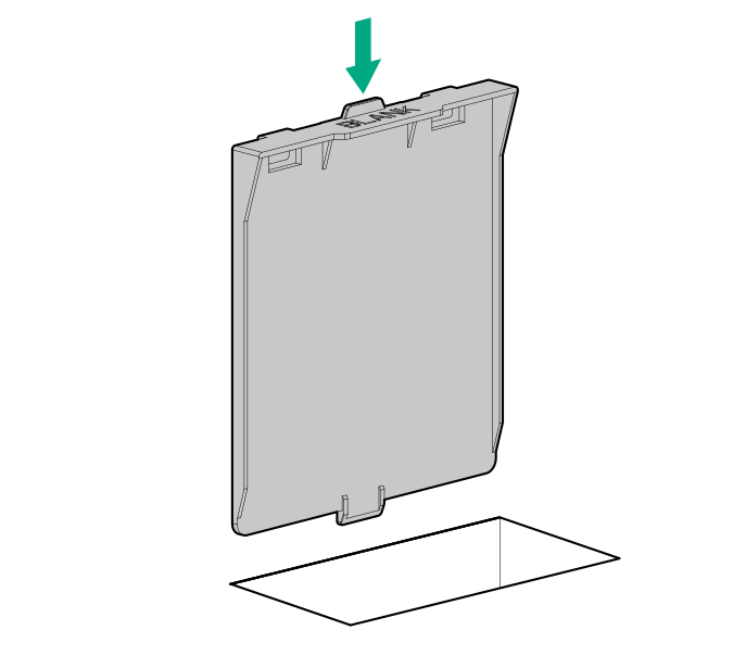
    2. Install the fan blank in bay 1.

      Installing the fan blank
    3. Make sure that the blank is firmly seated in the bay.
    4. Make sure that all the system cables that are routed through the front cable channel are properly secured in the metal cable tabs.

      This is done to prevent system damage due to cables being inadvertently caught under the fan cage.

    5. Install the fan cage.

    Since the fan 1 was replaced by a fan blank, redundant fan mode is no longer supported in this configuration.

  17. Install the air baffle.
  18. Install the access panel.
  19. Do one of the following:
  20. Connect all peripheral cables to the server.
  21. Connect each power cord to the server.
  22. Connect each power cord to the power source.
  23. Power up the server.
  24. Install the front bezel.
  25. Perform the verification and configuration procedures required by the drive option.

    For more information, see the drive user guide from the Storage section of the Hewlett Packard Enterprise Information Library.

The installation is complete.