RPS link board
Prerequisites
Before you perform this procedure, make that you have T-15 Torx screwdriver available.
T-15 screwdriver
- Power down the system.
- Disconnect all peripheral cables from the nodes and chassis.
- Remove all nodes from the chassis.
- If installed, remove the RCM module.
- Remove all power supplies.
- If installed, remove the security bezel.
- Remove all drives.
- Remove the chassis from the rack.
- Remove the access panel.
- If a Smart Storage Battery is installed, slightly pull up the battery holder from the chassis to access the battery cable connection underneath it, and then disconnect the Smart Storage Battery cable.
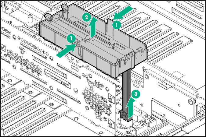
- Remove the PDB assembly.
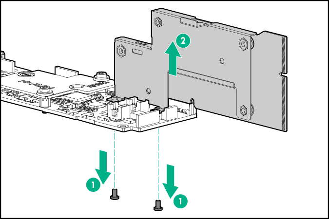
- Use a T-15 Torx screwdriver to remove the RPS link board bracket screws.
Disconnect the RPS link board from the PDB.
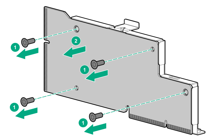
Use a T-15 Torx screwdriver to remove the RPS link board screws.
- Remove the RPS link board from its metal bracket.
To replace the component, reverse the removal procedure.