Remove the bayonet board assembly
- Power down the node.
- Disconnect all peripheral cables from the
node
.
- Remove the node from the chassis.
- Place the node on a flat, level surface.
- If installed in a 2U node,
remove the FlexibleLOM 2U node riser cage assembly.
- If installed in a 2U node,
remove the three-slot PCI riser cage assembly.
- If an accelerator power cable is installed, disconnect it from the bayonet board.
- If a B140i SATA cable is installed, disconnect it from the system board.
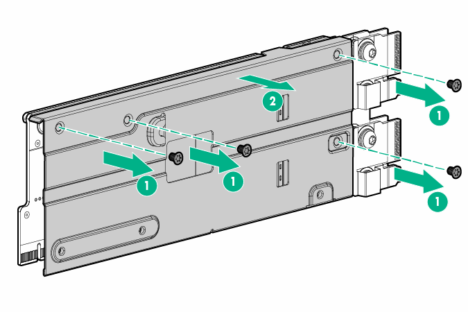
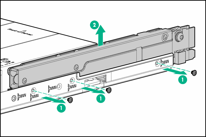
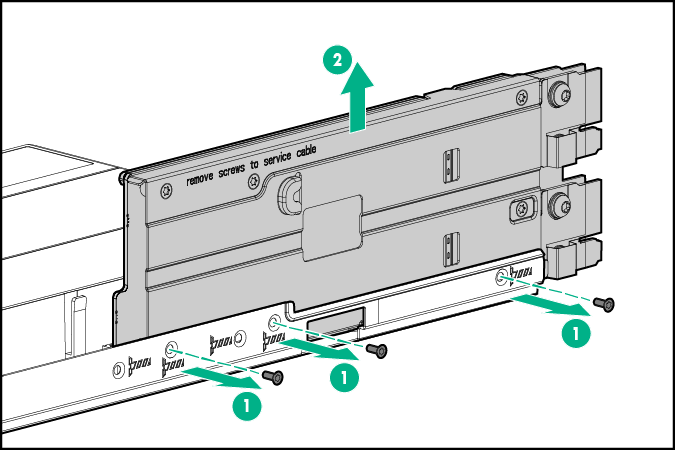
- Remove the bayonet board assembly from the node.
- 1U bayonet board assembly
- 2U bayonet board assembly
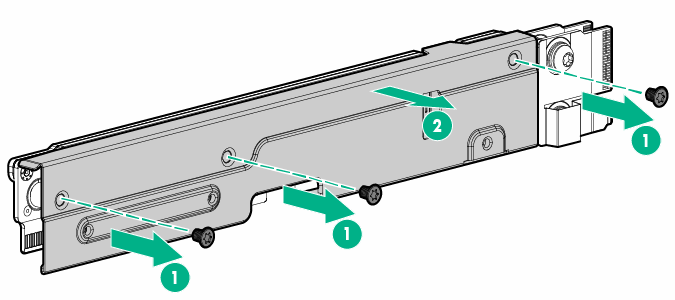
- If installing a SATA or Mini-SAS cable, remove the bayonet board bracket from the bayonet board.
- 1U bayonet board bracket
- 2U bayonet board bracket