System board
WARNING: To reduce the risk of personal injury from hot surfaces, allow the drives and the internal system components to cool before touching them.
CAUTION: To prevent damage to electrical components, take the appropriate anti-static precautions before beginning any installation, removal, or replacement procedure. Improper grounding can cause electrostatic discharge.
CAUTION: To avoid ESD damage, when removing electrostatic-sensitive components from the failed system board, place the components on a static-dissipating work surface or inside separate antistatic bags.
To remove the system board:
Procedure
-
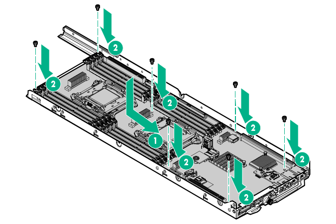
Remove the heatsink:
- Remove the heatsink from the processor backplate.
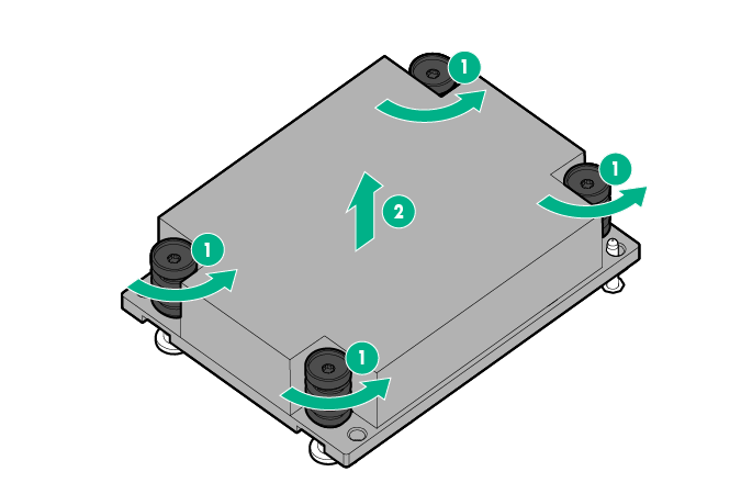
- Remove the heatsink from the processor backplate.
-
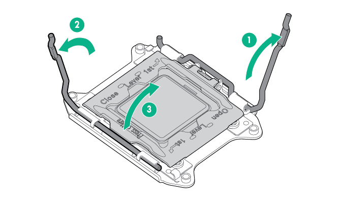
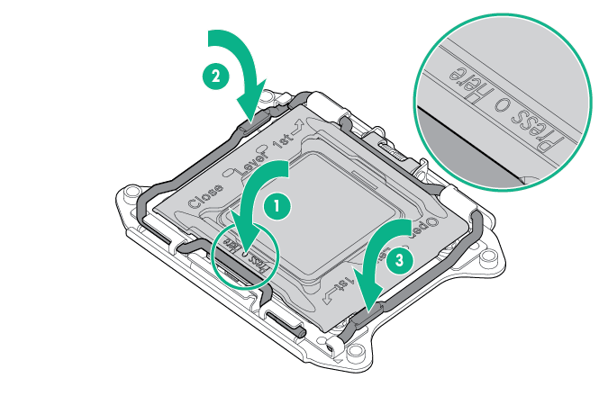
Open each of the processor locking levers in the order indicated, and then open the processor retaining bracket.
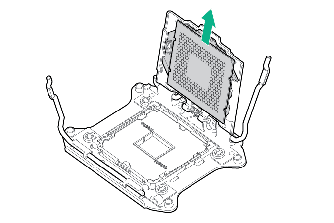
 CAUTION: THE PINS ON THE SYSTEM BOARD ARE VERY FRAGILE AND EASILY DAMAGED. To avoid damage to the system board, do not touch the processor or the processor socket contacts.
 -
Remove the processor from the processor retaining bracket.
-
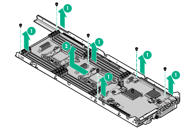
Remove the failed system board.
To replace the system board:
- Install the system board.
- Install the processor. Verify that the processor is fully seated in the processor retaining bracket by visually inspecting the processor installation guides on either side of the processor.
THE PINS ON THE SYSTEM BOARD ARE VERY FRAGILE AND EASILY DAMAGED.
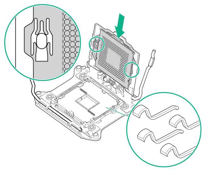 CAUTION: THE PINS ON THE SYSTEM BOARD ARE VERY FRAGILE AND EASILY DAMAGED. To avoid damage to the system board, do not touch the processor or the processor socket contacts.CAUTION: Do not press down on the processor. Pressing down on the processor might damage the processor socket and the system board. Press only in the area indicated on the processor retaining bracket.
 - Close the processor retaining bracket. When the processor is installed properly inside the processor retaining bracket, the processor retaining bracket clears the flange on the front of the socket.
- Press and hold the processor retaining bracket in place, and then close each processor locking lever. Press only in the area indicated on the processor retaining bracket.
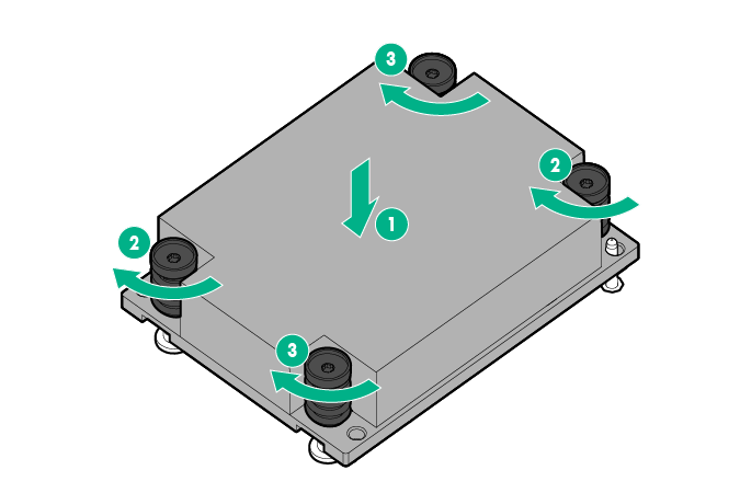
- Install the heatsink:
- Position the heatsink on the processor backplate.
- Tighten one pair of diagonally opposite screws halfway, and then tighten the other pair of screws.
- Finish the installation by completely tightening the screws in the same sequence.
- Install all components removed from the failed system board.
- Install the air baffle.
- Install the bayonet board assembly into the node.
- If any SATA or Mini-SAS cables are installed, secure the cables under the thin plastic covers along the side of the node tray.
- Connect all cables disconnected from the failed system board.
- Install any removed PCI riser cage assemblies and rear I/O blanks.
- Install the node into the chassis.
- Connect all peripheral cables to the nodes.
- Press the Power On/Standby button.
The node exits standby mode and applies full power to the system. The system power LED changes from amber to green.