Fanuc CNC Ethernet
Estimated reading time: 4 minutes
Refer to these sections for details:
Supported Series
FANUC 0i/30i/31i/32i/35i
Website: http://www.fanucfa.com/welcome_worldwide/
PLC Connection Settings
| Parameters | Recommended | Options | Notes |
|---|---|---|---|
| PLC Type | FANUC 0i/30i/31i/32i/35i Series (Ethernet) | ||
| PLC Interface | Ethernet | ||
| Port # | 8193 | ||
| PLC Station # | 1 | ||
PLC Configuration
Supported Data Types
Supported data types by FANUC and OT Link Platform. Below is for the FANUC PMC (Programmable Machine Control). Note: FANUC Macro variables support the FLOAT data type.
| Data Type | Size |
|---|---|
| BYTE | 1 byte |
| WORD | 2 bytes |
| Signed Value | Data Type | Size |
|---|---|---|
| INT8 | SINT | 1 byte |
| INT16 | INT | 2 bytes |
| INT32 | DINT | 4 bytes |
| Unsigned Value | Data Type | Size |
|---|---|---|
| UINT8 | USINT | 1 byte |
| UINT16 | UINT | 2 bytes |
| UINT32 | UDINT | 4 bytes |
The FANUC PMC System is the interface between the FANUC CNC and the machine tool. For information on the PMC system, take a look at the FANUC Corporation website.
RDPMC Tags
RDPMC tags provide all information about the Address Type, the Address Number to read data from, and Size within the tag itself.
Address Types:
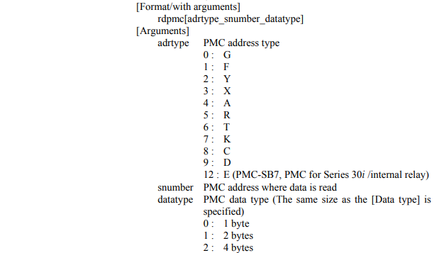
Example of RDPMC tag:
| Tag | Address Type | Address Number | Size |
|---|---|---|---|
| Rdpmc [9_746_2] | D | 746 | 4 bytes |
In the previous example, 9 refers to an address type listed in the image, 746 is the address number to read data from, and 2 means that the data is four bytes long.
OT Link Platform DeviceHub Configuration
To configure DeviceHub for this Fanuc PLC:
-
DeviceHub > Add Device
Type: Fanuc Corporation
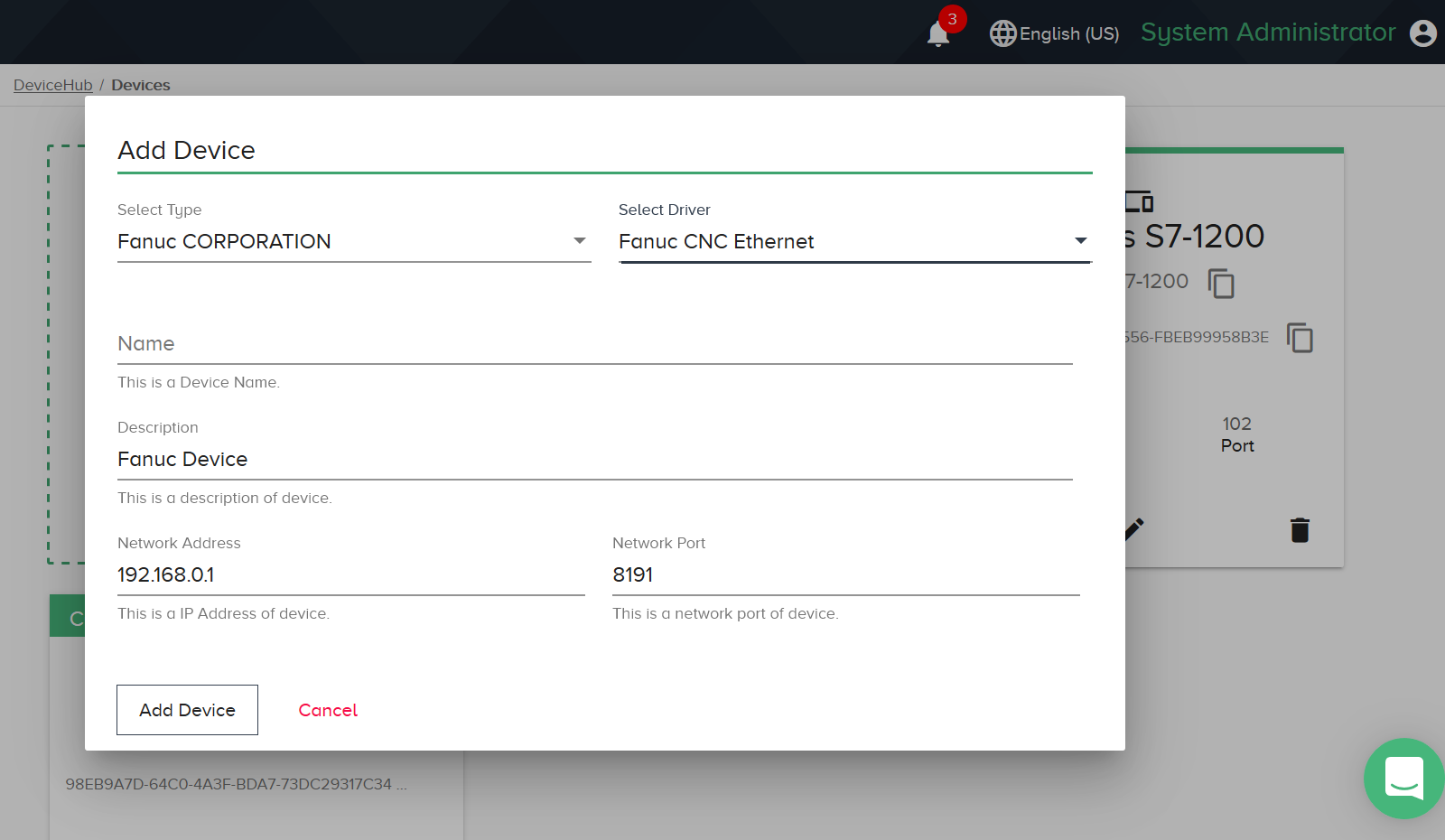
Driver: Fanuc CNC Ethernet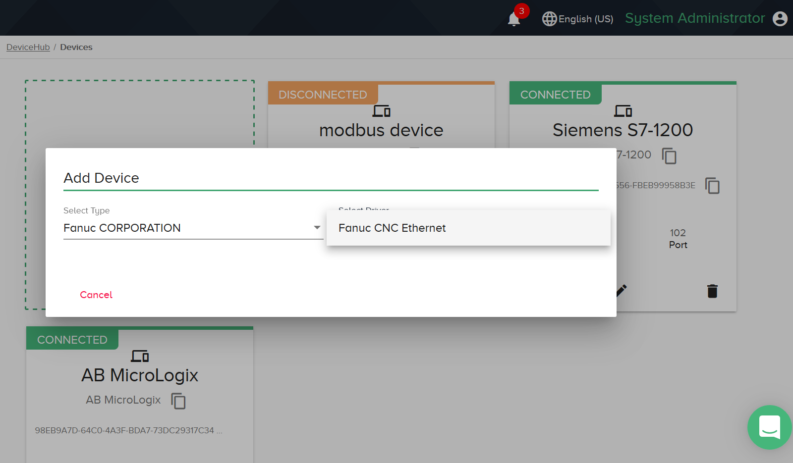
-
Enter details specific to your environment and click Add Device.
Device Addresses
|
Bit/Word |
Device Type |
Format |
Range |
Memo |
|---|---|---|---|---|
|
B |
G_Bit |
DDDDo |
0 ~ 999977 |
|
| B | F_Bit | DDDDo | 0 ~ 99997 | |
| B | Y_Bit | DDDDo | 0 ~ 99997 | |
| B | X_Bit | DDDDo | 0 ~ 99997 | |
| B | A_Bit | DDDDo | 0 ~ 99997 | |
| B | R_Bit | DDDDo | 0 ~ 99997 | |
| B | T_Bit | DDDDo | 0 ~ 99997 | |
| B | K_Bit | DDDDo | 0 ~ 99997 | |
| B | C_Bit | DDDDo | 0 ~ 99997 | |
| B | D_Bit | DDDDo | 0 ~ 99997 | |
| W | G | DDDD | 0 ~ 9999 | |
| W | F | DDDD | 0 ~ 9999 | |
| W | Y | DDDD | 0 ~ 9999 | |
| W | X | DDDD | 0 ~ 9999 | |
| W | A | DDDD | 0 ~ 9999 | |
| W | R | DDDD | 0 ~ 9999 | |
| W | T | DDDD | 0 ~ 9999 | |
| W | K | DDDD | 0 ~ 9999 | |
| W | C | DDDD | 0 ~ 9999 | |
| W | D | DDDD | 0 ~ 9999 | |
| W |
Absolute Position |
D | 1 ~ 8 | |
| W | Machine Position | D | 1 ~ 8 | |
| W | Relative Position | D | 1 ~ 8 | |
| W | Distance To Go | D | 1 ~ 8 | |
| W | Actual Spindle Speed | D | 0 ~ 1 | |
| W | Feed Rate | D | 0 | |
| W | MACRO VALUE | DDDD | 1 ~ 9999 |